Medical anesthetic liquid medicine bottle crushing device
A crushing device and anesthesia solution technology, applied in the direction of electric operation device, manual cutting device, application, etc., can solve the problems of low efficiency and easy injury
- Summary
- Abstract
- Description
- Claims
- Application Information
AI Technical Summary
Problems solved by technology
Method used
Image
Examples
Embodiment 1
[0036] A kind of crushing device for medical anesthesia liquid medicine bottle, such asfigure 1 and figure 2 As shown, it includes a bottom plate 1 , a supporting mechanism 2 and a pressing mechanism 3 , the supporting mechanism 2 is arranged on the top of the bottom plate 1 , and the pressing mechanism 3 is connected between the bottom plate 1 and the supporting mechanism 2 .
[0037] When the user needs to break the medicine bottle, this device can be used. First, the medicine bottle to be broken is placed in the support mechanism 2, and then the user can press the parts of the pressing mechanism 3 to make the pressing mechanism 3 The operation is carried out, and the medicine bottle is crushed by the pressing mechanism 3 . After the crushing is completed, the user can take out the broken medicine bottle from the support mechanism 2 .
Embodiment 2
[0039] On the basis of Example 1, such as image 3 and Figure 4 As shown, the support mechanism 2 includes a frame 20, a seating seat 21 and a medicine bottle holder 22, the frame 20 is arranged on the rear side of the upper part of the bottom plate 1, and the bottom plate 1 is provided with a sliding seat 21 in the middle of the upper part, and a medicine bottle is placed on the top of the seating seat 21. Rack 22.
[0040] The user can remove the seat 21 and the vial rack 22, and then place the broken vial in the vial rack 22, and then move the seat 21 and the vial rack 22 to reset.
[0041] Pressing mechanism 3 comprises cover plate 30, first movable frame 31, first spring 32, first rack 33, support frame 34, rotating shaft 35, full gear 36, second rack 37, push plate 38, triangular block 39. The first fixed block 310, the movable ball 311, the second spring 312, the one-way gear 313 and the third spring 314, the front side of the frame 20 is slidingly provided with the ...
Embodiment 3
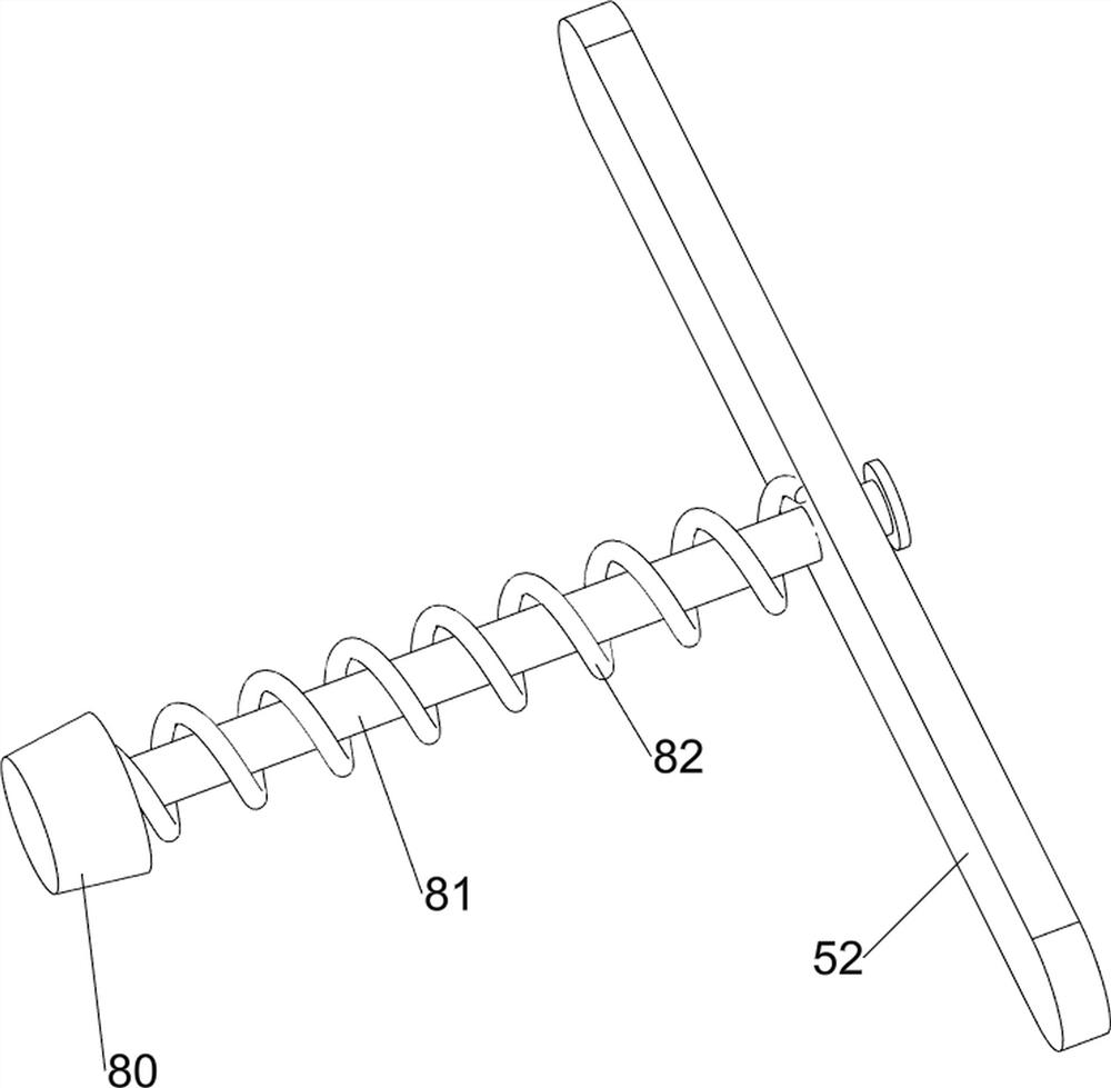
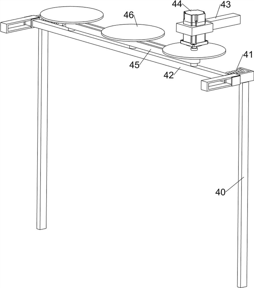
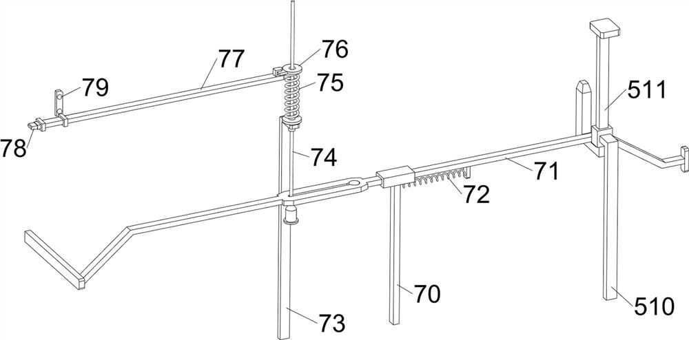
[0044] On the basis of Example 2, such as Figure 5-13 As shown, a cutting mechanism 4 is also included, and the cutting mechanism 4 includes a first support rod 40, a linear spring 41, a sliding rod 42, a telescopic rod 43, a servo motor 44, a transmission assembly 45 and a saw blade 46, and the upper rear side of the base plate 1 Left-right symmetrical type is provided with the first support rod 40, and sliding type is provided with the slide rod 42 between the first support rod 40 on both sides, is connected with the linear spring 41 between the slide rod 42 and the first support rod 40, frame 20 front The right side is provided with telescopic rod 43, is connected with servomotor 44 on telescopic rod 43, is all provided with saw blade 46 on the output shaft of servomotor 44 and slide bar 42, saw blade 46 is connected with slide rod 42 rotationally, saw blade The number of 46 is three, and the transmission assembly 45 is connected between the output shaft of the servo motor...
PUM
 Abstract
Description
Claims
Application Information
 - R&D
- Intellectual Property
- Life Sciences
- Materials
- Tech Scout
- Unparalleled Data Quality
- Higher Quality Content
- 60% Fewer Hallucinations
Browse by: Latest US Patents, China's latest patents, Technical Efficacy Thesaurus, Application Domain, Technology Topic, Popular Technical Reports.
© 2025 PatSnap. All rights reserved.Legal|Privacy policy|Modern Slavery Act Transparency Statement|Sitemap|About US| Contact US: help@patsnap.com


