Feed throwing device for fishery breeding
A feed and fishery technology, applied in the field of aquaculture equipment, can solve the problems of limited feed throwing range, agglomerated feed crushing, etc., and achieve the effect of avoiding uneven feed throwing and strengthening the crushing effect
- Summary
- Abstract
- Description
- Claims
- Application Information
AI Technical Summary
Problems solved by technology
Method used
Image
Examples
Embodiment 1
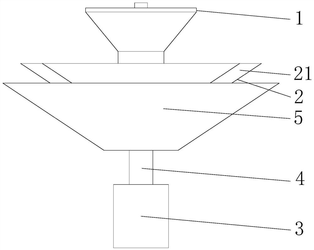
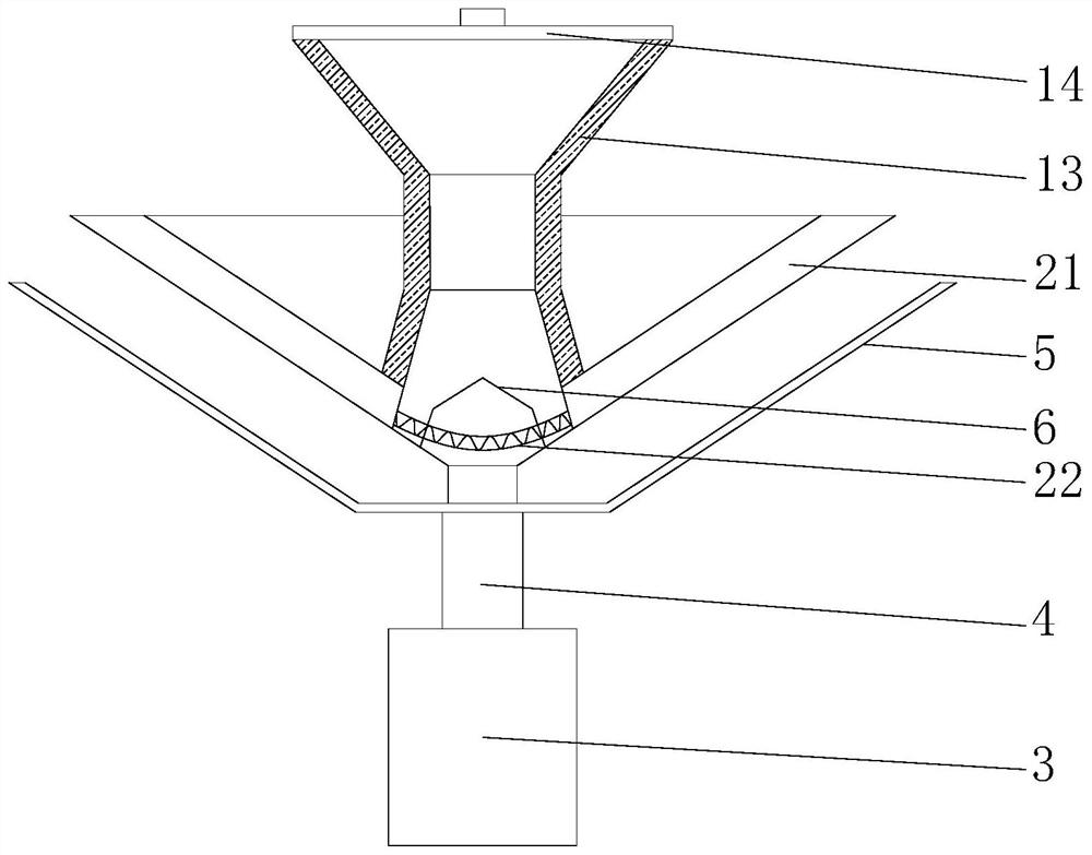
[0030]Such asFigure 1 - Figure 2 As shown, the present invention provides a feed throwing device for fishery breeding, including a sheet mechanism 1 and a crushing mechanism 2, in the present embodiment, the upper body 1 includes a storage box 12, a top thread connection of the storage case 12. There is a cover 14, the inner wall of the storage box 12 has a dry bin 13, and the feed port 11 uses a reverse trapezoidal arrangement. The inverted structure is convenient to accumulate, and the inverted lane is more feeding, By using the bonding mechanism 1 and the second hopper, it is convenient for the feed to perform a wide range of throws, and the motor 3 is rotated by the motor 3, and the direction of the feed extension roller groove 51 is used in the form of a parabolic according to the size of the speed by centrifugation force. Throwing feed in the fish pond, avoiding the phenomenon of non-uniform feed, and due to the size of the speed of the speed, the feed shower range is differen...
Embodiment 2
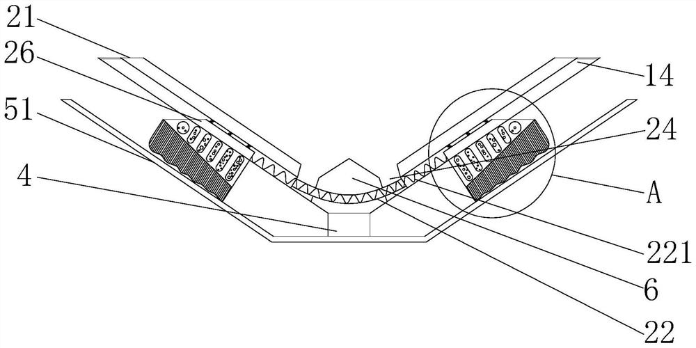
[0033]Such asFigure 6-7 As shown in the basis of the first embodiment, the present invention provides a technical solution: the number of internal metal balls 232 of each cavity 231 is not equal, and the weight of each metal ball 232 is not equal, each The inner wall of the cavity 231 is fixedly coupled with metal insert 234, wherein the metal ball 232 inside the cavity 231 produces a larger amplitude when impacted with the metal balance 234, and a plurality of cavities are provided inside the single connecting plate 23. 231. The number of metal balls 232 inside the cavity 231 increases the weight in order to increase the weight, and the number of metal balls 232 in the symmetrical connecting plate 23 is also different, and the bottom of the two connection plates 23 passes through the first spring 221 through the first spring 221. The rod 22 is connected inside, and since the collision of the metal ball 232 causes a difference in the rotational speed of the first bucket 21 and the s...
Embodiment 3
[0035]Such asFigure 1-5As shown, in the basis of Example 1, Example 2, the present invention provides a technical solution: preferably, the bottom of the first material 21 is opened, and the bottom bouting 21 is fixed at both ends. The connecting rod 22, the interior of the connecting rod 22 is connected to the first spring 221, and the connecting rod 22 is connected to the connecting block 6. The bottom rotation of the connecting block 6 is rotatably connected to the shaft 4, and the bottom rotation of the rotating shaft 4 is rotated and connected to the motor 3, and the rotary axis 4 The inner wall of the second hopper 5, the inner wall of the second hopper 5 is provided, and the second spring 233 has a downward force due to the centrifugal force, so that the second spring 233 is made of the second spring 233 due to the centrifugal force. There must be a certain pressure on the connecting plate 23, and the bristles 27 are tightly bonded to the outer wall of the first bracket 21, a...
PUM
 Abstract
Description
Claims
Application Information
 - R&D Engineer
- R&D Manager
- IP Professional
- Industry Leading Data Capabilities
- Powerful AI technology
- Patent DNA Extraction
Browse by: Latest US Patents, China's latest patents, Technical Efficacy Thesaurus, Application Domain, Technology Topic, Popular Technical Reports.
© 2024 PatSnap. All rights reserved.Legal|Privacy policy|Modern Slavery Act Transparency Statement|Sitemap|About US| Contact US: help@patsnap.com


