
Positioning device for machining

A positioning device and machining technology, used in positioning devices, metal processing equipment, metal processing mechanical parts, etc., can solve the problems of affecting positioning efficiency, low positioning accuracy, difficult positioning, etc. Strong adjustment and good fixing effect

Inactive Publication Date: 2021-05-28
戴鸿
View PDF0 Cites 0 Cited by
  • Summary
  • Abstract
  • Description
  • Claims
  • Application Information

AI Technical Summary

Problems solved by technology

However, at present, the positioning of workpieces is generally done manually, which is inefficient in positioning, and the positioning of ordinary positioning blocks is basically achievable for some structures where the positioning reference is on a plane. For some workpieces with irregular shapes, it is often difficult to perform comprehensive positioning due to their positioning references, which makes it difficult to accurately limit the degree of freedom when positioning them, resulting in low positioning accuracy and affecting positioning efficiency.

Method used


Image

  • Positioning device for machining
  • Positioning device for machining
  • Positioning device for machining

Examples


Embodiment 1

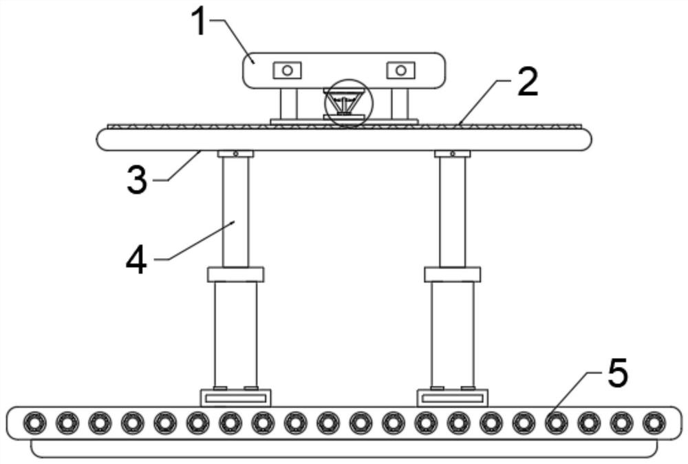
[0024] see Figure 1~6 , in an embodiment of the present invention, a positioning device for machining, including a fixture 1; the fixture 1 is installed on the top of a mounting plate 31; The top of the fixture 1 is provided with a clamping and fixing assembly; the workbench 3 is connected to the bottom plate 5 through an adjustable regulator 4; there are four adjustable regulators 4.

[0025] In this embodiment, the fixer 1 includes a housing; the front inner wall and the rear inner wall of the housing are provided with corresponding clamping and fixing components.

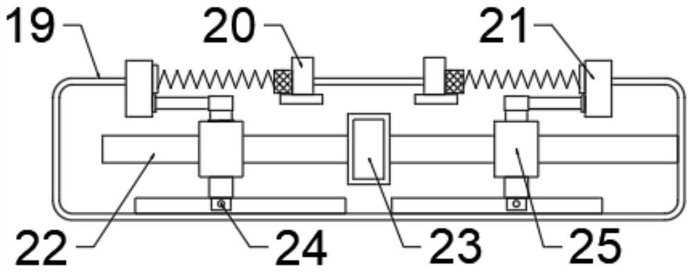
[0026] In this embodiment, the clamping and fixing assembly includes a fixed installation plate 19 arranged along the horizontal direction; the vertical centerline of the fixed installation plate 19 is provided with a guide rod 22 arranged along the horizontal direction; The back side of the guide rod 22 is connected to the fixed mounting plate 19 through a fixed rod; the central part of the guide rod 22 is fix...

Embodiment 2

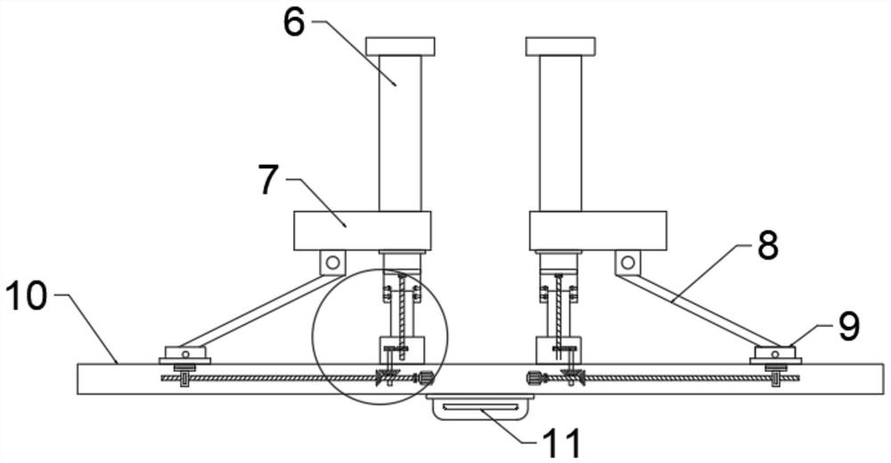
[0030] see figure 2Or 4, in the embodiment of the present invention, the adjustable controller 4 includes a connecting rod 6; the top end of the connecting rod 6 is hinged to the bottom of the workbench 3; the bottom end of the connecting rod 6 is fixedly connected to the top of the installation box 7; The bottom of the installation box 7 is equipped with a fixed cylinder 12; the inner wall of the fixed cylinder 12 is provided with a guide block 14 in the vertical direction of the center line in the horizontal direction of the horizontal plane; the guide block 14 is slidably connected to the adjustment cylinder 13 The guide chute in the vertical direction on the outer wall; the inner bottom end of the fixed cylinder 12 is connected to the top end of the threaded rod 15 through a rotating bearing; A gear set 16; the first gear set 16 includes a No. 1 gear and a No. 2 gear; the No. 1 gear is arranged on the threaded rod 15 and is meshed and connected to the No. 2 gear on the co...


PUM


Abstract

The invention discloses a positioning device for machining. The positioning device comprises a fixator. the fixator is mounted at the top of a mounting plate; the mounting plate is arranged at the top of a placement plate fixedly mounted on a workbench; a clamping and fixing assembly is arranged on the fixer; the workbench is connected with a bottom plate through adjustable devices; and the number of the adjustable devices is four. The device is high in adjustability, good in fixing effect and high in positioning accuracy.

Description

technical field [0001] The invention relates to the technical field of machining, in particular to a positioning device for machining. Background technique [0002] Mechanical parts need to be positioned during processing, and drilling and cutting operations can only be performed after the parts are positioned. However, at present, the positioning of workpieces is generally done manually, which is inefficient in positioning, and the positioning of ordinary positioning blocks is basically achievable for some structures where the positioning reference is on a plane. For some workpieces with irregular shapes, it is often difficult to perform comprehensive positioning due to their positioning references, which makes it difficult to accurately limit the degree of freedom when positioning them, resulting in low positioning accuracy and affecting positioning efficiency. . [0003] Therefore, in view of the above current situation, it is urgent to develop a positioning device for ...

Claims


Application Information

Patent Timeline
IPC IPC(8): B23Q3/08B23Q3/18B23Q1/25
CPCB23Q1/25B23Q3/082B23Q3/18
Inventor 戴鸿
Owner 戴鸿
Learn More