
Intravascular optical coherence tomography laser ablation catheter

A technology of optical coherence tomography and laser ablation, applied in the direction of catheter, tomography for diagnosis, diagnosis, etc., to shorten the imaging time and protect the blood vessel wall.

Inactive Publication Date: 2021-05-28
BEIHANG UNIV
View PDF8 Cites 5 Cited by
  • Summary
  • Abstract
  • Description
  • Claims
  • Application Information

AI Technical Summary

Problems solved by technology

There are currently no catheters or similar products that combine intravascular imaging and laser ablation

Method used


Image

  • Intravascular optical coherence tomography laser ablation catheter
  • Intravascular optical coherence tomography laser ablation catheter
  • Intravascular optical coherence tomography laser ablation catheter

Examples


specific Embodiment approach 1

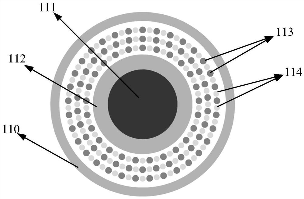
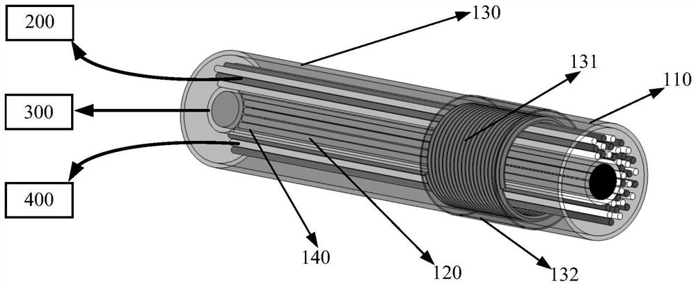
[0027] The central aperture (111) at the head end of the catheter tube is used to pass through the guide wire to reach the lesion, and the aperture size may be 0.3-0.4mm. The outer pore (112) of the central aperture at the head end of the catheter can be an injection port for physiological saline, and the size of the pore can be 0.1-0.2 mm. Controlling the injection time and injection speed of saline can effectively reduce the possibility of damage to the vessel wall during the thermal relaxation generated by the laser. Finally, the diameter of the entire catheter can be controlled within 1.5-2.0 mm, and can smoothly pass through the vascular cavity of the large artery in the blood vessel for imaging and laser ablation.

specific Embodiment approach 2

[0029] Based on the physiological saline injection port (112) in the specific embodiment one, it can be a miniature temperature measuring device introduction port. Its miniature temperature measuring device can be a thermocouple and a miniature temperature sensor, which can detect the temperature change in the blood vessel during laser ablation.

specific Embodiment approach 3

[0031] The intravascular optical coherent imaging fiber (113) used in the catheter can be a graded index fiber, and the fiber for laser ablation (114) can be a multi-wavelength fiber. Flexibility for imaging and treatment within the vessel is maintained through the use of multiple small optical fibers. The fiber must be totally reflected in the core and the cladding. Considering that the core-to-cladding ratio of the fiber is 1:1.05 or 1:1.10, the core diameter of the small fiber can be controlled between 40-100 microns. In order to ensure the softness and flexibility of the catheter, the total number of optical fibers arranged in the entire catheter shall not exceed 250, and the number of optical fibers may be controlled at 100-200 according to the size of the catheter.


PUM

PropertyMeasurementUnit
Lengthaaaaaaaaaa
Diameteraaaaaaaaaa

Abstract

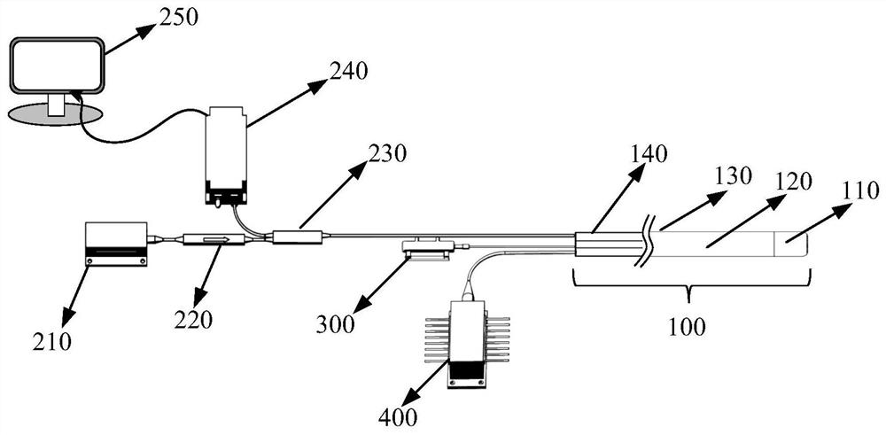
The invention provides an intravascular optical coherence tomography laser ablation catheter which adopts all-fiber array type arrangement and double-hollow type design and is used for imaging and real-time ablation treatment of intravascular lesions. The catheter comprises a catheter head end, a catheter wall part, a catheter cavity part and a catheter tail end. The circular aperture in the center-most portion of the catheter is a guide wire aperture allowing the catheter to flexibly pass through the guide wire. An annular hole is formed in the periphery of the circular hole in the center of the catheter and serves as a normal saline injection hole, and normal saline injection or introduction of other miniature temperature measuring equipment is allowed. A plurality of optical fibers used for optical coherence tomography and laser ablation are sequentially arranged in the catheter in an adjacent concentric circle array mode. A miniature spring and a flexible material are arranged inside and outside the catheter wall to control the bending angle of catheter imaging and treatment. By means of the design of the catheter, the imaging speed in the blood vessel can be increased, and imaging in the blood vessel and treatment in the blood vessel are better combined.

Description

[0001] (1) Technical field [0002] The invention relates to the field of medical devices, in particular to an intravascular optical coherence tomography laser ablation catheter. [0003] (2) Background technology [0004] Cardiovascular disease is the number one cause of death worldwide, and more people die each year from cardiovascular disease than from other causes of death. According to the World Health Organization, about 17.9 million people died of cardiovascular diseases in 2016, accounting for 31% of the total global deaths. Since 2017, cardiovascular disease death has been the first cause of death among urban and rural residents in China. The occurrence of cardiovascular diseases has a great relationship with the obstruction of blood transport in blood vessels. A large part of the obstruction of blood transport is due to the formation of atherosclerotic plaques, which rupture and cause blood clots that block blood vessels. Therefore, it is necessary to ablate the pl...

Claims


Application Information

Patent Timeline
IPC IPC(8): A61B18/24A61B5/00
CPCA61B5/0066A61B5/0073A61B5/0084A61B18/245A61B2018/00345A61B2018/00982A61B2018/2211A61B2218/002
Inventor 付博吉训明李静徐立军尚策王子皓张奡杰
Owner BEIHANG UNIV
Learn More