Camera module and manufacturing method of circuit board in camera module

A camera module and circuit board technology, applied in the optical field, can solve the problems of different circuit board materials, temperature drift, etc., and achieve the effect of solving temperature drift, improving resolution and reliability

Pending Publication Date: 2021-05-25
ZHEJIANG SUNNY SMARTLEAD TECH CO LTD
View PDF0 Cites 0 Cited by
  • Summary
  • Abstract
  • Description
  • Claims
  • Application Information

AI Technical Summary

Problems solved by technology

[0003] The purpose of the present invention is to solve the above problems, provide a camera module and a method for making circuit boards in the camera module, and solve the problem of temperature drift caused by different circuit board materials

Method used


Image

  • Camera module and manufacturing method of circuit board in camera module
  • Camera module and manufacturing method of circuit board in camera module
  • Camera module and manufacturing method of circuit board in camera module

Examples


Embodiment approach

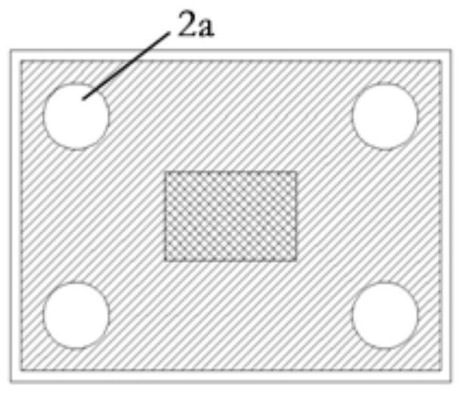
[0032]Such asFigure 4 As shown, according to a second embodiment of the present invention, the mounting boss 11 of the present invention is disposed such that the mounting through hole 2a is provided as a rectangular hole, and two mounting through holes 2a, two mounting holes 2a, two mounting The through hole 2a extends in the width direction of the wire panel 2.

[0033]Such asFigure 5 As shown, according to a third embodiment of the present invention, the mounting boss 11 of the present invention is disposed such that the mounting through hole 2a is provided as a rectangular hole, and two mounting through holes 2a are provided on the circuit board 2, two mounting The through hole 2a extends in the longitudinal direction of the wire panel 2.

[0034]Such asFigure 6 As shown, according to a fourth embodiment of the present invention, the mounting boss is disposed as an L-shaped structure, and the mounting through hole 2a is adapted to the shape of the mounting boss 11. The mounting throug...


PUM


Abstract

The invention relates to a camera module and a manufacturing method of a circuit board in a camera module, the camera module comprises a lens (1) and a circuit board, the circuit board comprises a circuit board part (2) and a reinforcing flat plate (3) fixed on the circuit board part (21), the lower end of the lens (1) is provided with a mounting boss (11), and the mounting boss (11) is provided with a mounting hole (12). The circuit board part (2) is provided with installation through holes (2a) matched with the installation bosses (11), and the installation bosses (11) penetrate through the installation through holes (2a) to be fixedly connected with the reinforcing flat plate (3). According to the camera module, the mounting boss is arranged at the lower end of the lens, the mounting through hole is formed in the circuit board, and the mounting boss of the lens penetrates through the mounting through hole to be directly fixed to the surface of the reinforcing flat plate, so that the assembling mode of a traditional camera module is changed, and meanwhile, the problem of temperature drift caused by deformation of the circuit board due to temperature influence can be solved; and the resolution and the reliability of the camera module can be improved.

Description

Technical field[0001]The present invention relates to the field of optics, and more particularly to a method of fabricating an imaging module and an imaging module circuit board.Background technique[0002]Currently, the market is getting higher and higher for various camera modules. For example, with the improvement of intelligent driving registration, the demand force, warm drift stability and reliability of the ADAS (Advanced Driving Assistant System) Camera, and the lens of the existing ADAS camera module is usually directly related to the line. The plate is connected, in this case, due to the difference in the expansion coefficient of the circuit board material (e.g., FR4, BT, polyimide, etc.), and the working temperature affects the fact that there is a variable variable, thereby causing a camera mode. The problem that the temperature drift is too large or the drifting is difficult to compensate, and it ultimately leads to a problem of poor consistency in the imaging module.Inve...

Claims


Application Information

Patent Timeline
Patent Type & Authority Applications(China)
IPC IPC(8): H04N5/225H04N5/369
CPCH04N23/50H04N25/79
Inventor 郭巍张扣文祝预冲农开勋
Owner ZHEJIANG SUNNY SMARTLEAD TECH CO LTD
Why Eureka
Try Eureka