
Demux display screen driving circuit and control method thereof

A technology of driving circuit and control method, which is applied in the direction of static indicators, instruments, etc., can solve the problems of demux circuit driving force drop, affect the display effect, and display unevenness, so as to solve the uneven display of the screen, improve the display effect, and improve driving force effect

Pending Publication Date: 2021-05-25
FUJIAN HUAJIACAI CO LTD
View PDF3 Cites 0 Cited by
  • Summary
  • Abstract
  • Description
  • Claims
  • Application Information

AI Technical Summary

Problems solved by technology

However, as the usage time increases, the driving force of the Demux circuit will decrease, resulting in uneven display, thus affecting the display effect

Method used


Image

  • Demux display screen driving circuit and control method thereof
  • Demux display screen driving circuit and control method thereof
  • Demux display screen driving circuit and control method thereof

Examples


Embodiment 1

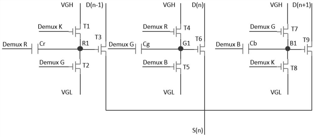
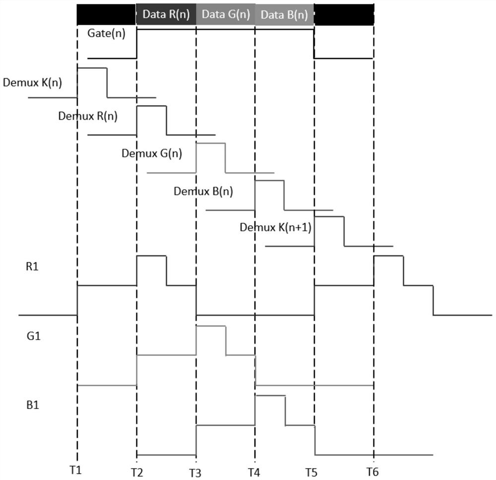
[0035]Please refer tofigure 1 withimage 3Embodiments of the present invention one as:

[0036]Please refer tofigure 1 A DEMUX display drive circuit includes a transistor T1, a transistor T2, a transistor T3, a transistor T4, a transistor T5, a transistor T6, a transistor T7, a transistor T8, a transistor T9, a capacitor CR, a capacitor CG, and a capacitor Cb, the transistor T1. The gate is connected to the first DEMUX control line, and the source of the transistor T1 is electrically connected to one end of the capacitor CR, the drain and the gate of the transistor T2 and the gate of the transistor CR, and the other end of the capacitor CR is connected to the second Demux control. Line, the gate of the transistor T2 is connected to the third Demux control line, the gate of the transistor T4, the second Demux control line, the source of the transistor T4, respectively, one end of the capacitor CG, the drain of the transistor T5 and The gate of the transistor T6 is electrically connected,...

Embodiment 2

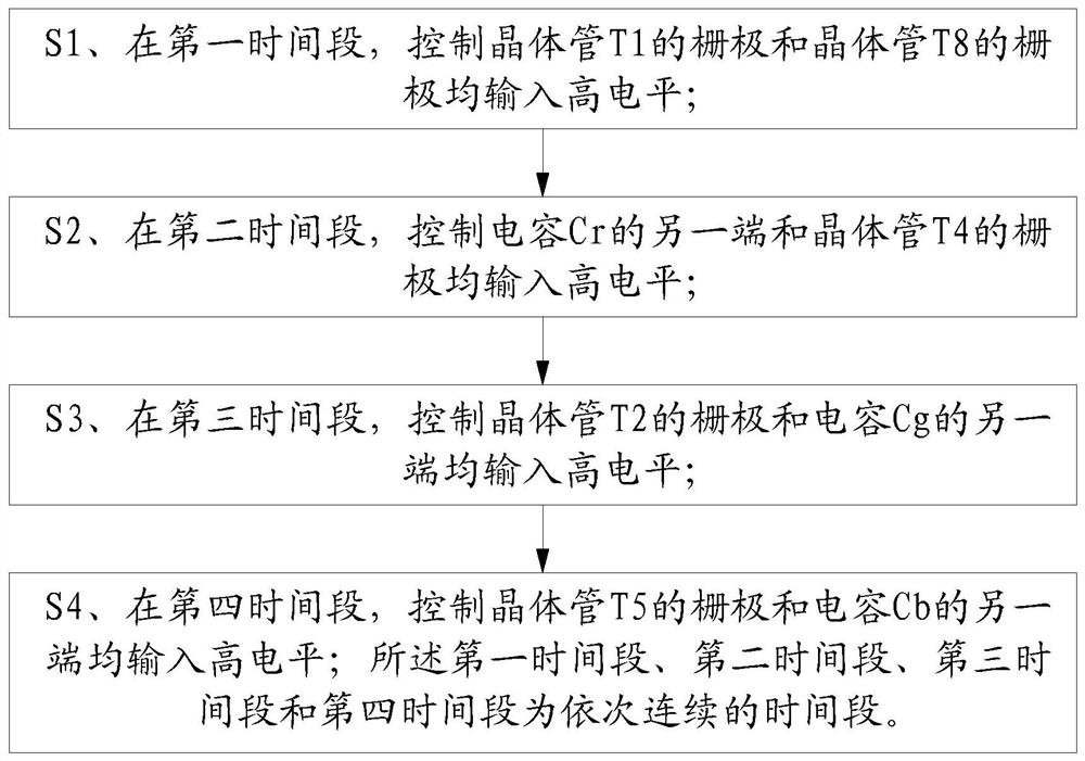
[0051]Please refer tofigure 2 withimage 3Embodiment 2 of the present invention:

[0052]A Demux Display Drive Circuit Control Method, including the following steps:

[0053]S1, in the first time period, the gate of the control transistor T1 and the gate of the transistor T8 are input to high level;

[0054]S2, in the second time period, the other end of the control capacitor CR and the gate of the transistor T4 are input to high level;

[0055]S3, in the third time period, the other end of the gate of the control transistor T2 and the capacitor CG inputs high level;

[0056]S4, in the fourth time period, the other end of the gate of the control transistor T5 and the other end of the capacitor Cb is input to high level; the first period, the second time period, the third time period, and the fourth time period are sequentially continuous. The time period.

[0057]Specific embodiment of the control method of the above DEMUX display drive circuit is:

[0058]The DEMUX display drive circuit designed in this...


PUM


Abstract

The invention relates to the technical field of Demux display screen driving circuits, in particular to a Demux display screen driving circuit and a control method thereof.The Demux display screen driving circuit comprises a transistor T1, a transistor T2, a transistor T3, a transistor T4, a transistor T5, a transistor T6, a transistor T7, a transistor T8 and a transistor T9, the grid electrode of the transistor T1 is connected with a first Demux control line, the grid electrode of the transistor T2 is connected with a third Demux control line. The grid electrode of the transistor T4 is connected with a second Demux control line, the grid electrode of the transistor T5 is connected with a fourth Demux control line, the grid electrode of the transistor T7 is connected with a third Demux control line, and the grid electrode of the transistor T8 is connected with a first Demux control line, so that the driving force of the Demux display screen driving circuit can be improved by improving the level of the control end of the Demux display screen driving circuit; therefore, the problem of non-uniform image display caused by Demux driving force reduction is solved.

Description

Technical field[0001]The present invention relates to the field of DEMUX display driving circuitry, and in particular, to a DEMUX display drive circuit and a control method thereof.Background technique[0002]Since the display of DEMUX (Decompress) drive technology has a narrow border, it is widely used. However, as the use time increases, the driving force of the DEMUX circuit will fall, resulting in uneven display, which affects the display effect.Inventive content[0003]The technical problem to be solved by the present invention is to provide a DEMUX display drive circuit and a control method thereof to improve the driving force of the DEMUX circuit, solving the poor display of Demux driving force, thereby improving the service life of the product.[0004]In order to solve the above technical problems, the first technical solution adopted by the present invention is:[0005]A DEMUX display drive circuit includes a transistor T1, a transistor T2, a transistor T3, a transistor T4, a trans...

Claims


Application Information

Patent Timeline
Patent Type & Authority Applications(China)
IPC IPC(8): G09G3/20
CPCG09G3/20
Inventor 谢建峰
Owner FUJIAN HUAJIACAI CO LTD
Learn More