
Spray ring with adjustable nozzle angle and air-assisted sprayer

A spray ring and nozzle technology, which is used in the separation of dispersed particles, chemical instruments and methods, and the use of liquid separation agents, can solve the problems of inability to realize real-time adjustment of airflow and mist flow, fixed angle, etc., and achieve a control method with less energy consumption, The effect of precise governance and various adjustment methods

Pending Publication Date: 2021-05-25
HUNAN JIU JIU MINING SAFETY EQUIP
View PDF0 Cites 6 Cited by
  • Summary
  • Abstract
  • Description
  • Claims
  • Application Information

AI Technical Summary

Problems solved by technology

[0010] Based on this, the present invention proposes a spray ring with an adjustable nozzle angle and an air-driven sprayer. Technical Problems of Real-time Adjustment of Relative Angle Between Airflow and Mist Flow

Method used


Image

  • Spray ring with adjustable nozzle angle and air-assisted sprayer
  • Spray ring with adjustable nozzle angle and air-assisted sprayer
  • Spray ring with adjustable nozzle angle and air-assisted sprayer

Examples


Embodiment 1

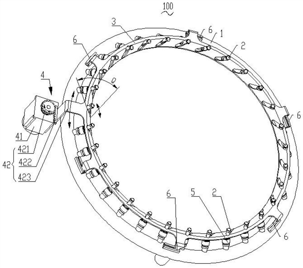
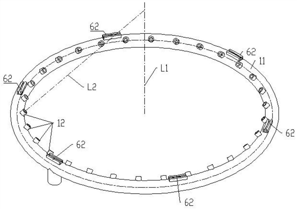
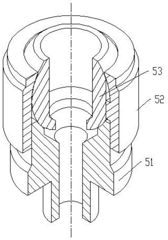
[0041] Reference attached Figure 1-6 , figure 1 The direction indicated by the arrow in the center is the moving direction of each component. Image 6 The direction indicated by the middle arrow is the height direction of the adjustment frame 3, a spray ring 100 with adjustable nozzle angle, including: spray ring pipe 1, nozzle 2, adjustment frame 3 and adjustment power part 4, the spray ring pipe 1 as a whole is Annular tubular, the adjustment frame 3 is provided with a waist-shaped groove 31 running through it, the angle between the extension direction of the waist-shaped groove 31 and the height direction of the adjustment frame 3 is Q, 0° Figure 9 , the nozzle 2 runs through the waist-shaped groove 31, and one end of the nozzle 2 is connected to the spray ring pipe 1 by a ball hinge, the adjustment frame 3 is slidingly connected with the spray ring pipe 1, and the adjustment power part 4 is used to drive the adjustment frame 3 along the spray ring The tube 1 slides back ...

Embodiment 2

[0052] Please focus on reference Image 6 , Image 6 The direction indicated by the middle arrow is the height direction of the adjustment frame 3 , and the arrow direction is also the telescopic direction of the linear power actuator 43 . A spray ring 100 with an adjustable nozzle angle, comprising: a spray ring pipe 1, a nozzle 2, an adjustment frame 3 and an adjustment power part 4. Shaped groove 31, the angle between the extending direction of the waist-shaped groove 31 and the height direction of the adjustment frame 3 is Q, 0°<Q<90°, the nozzle 2 runs through the waist-shaped groove 31, and one end of the nozzle 2 is connected to the spray ring pipe 1 They are connected by ball hinges, the adjustment frame 3 is slidingly connected with the spray ring pipe 1, and the adjustment power part 4 is used to drive the adjustment frame 3 to slide back and forth along the spray ring pipe 1 to change the angle of the nozzle 2. The adjusting power member 4 is a linear power actuat...


PUM


Abstract

The invention discloses a spray ring with adjustable nozzle angle. The spray ring comprises a spray ring pipe, a nozzle, an adjusting frame and an adjusting power part. The spray ring pipe is integrally in an annular pipe shape. A kidney-shaped groove penetrating through the adjusting frame is formed in the adjusting frame, and the included angle between the extending direction of the kidney-shaped groove and the height direction of the adjusting frame is an acute angle. The nozzle penetrates through the kidney-shaped groove, and one end of the nozzle is connected with the spraying ring pipe in a ball hinge mode. The adjusting frame is connected with the spray ring pipe in a sliding mode. The adjusting power part is used for driving the adjusting frame to slide back and forth along the spray ring pipe so as to change the angle of the nozzle. The invention further discloses an air-assisted sprayer which comprises a barrel and the spray ring with adjustable nozzle angle. The technical problem that in the prior art, the angle of a nozzle on a spray ring of an air-assisted sprayer is fixed, and the relative angle of airflow and mist flow cannot be adjusted in real time is solved.

Description

technical field [0001] The invention belongs to the technical field of spray dust suppression devices, in particular to a spray ring with an adjustable nozzle angle. Background technique [0002] The air-driven sprayer includes a fan, a spray ring, a booster pump, a controller, and a frame. The spray ring is located at the air outlet at the front of the fan, and the nozzle is installed on the spray ring. The atomization process is divided into a hydraulic atomization of the nozzle and There are two processes of secondary atomization of high-speed airflow, and the atomization forms and mechanisms of the two processes are quite different. The primary atomization is the pressure atomization process in which the liquid flows out of the nozzle under the action of pressure; the secondary atomization is the phenomenon that the liquid droplets are dispersed in the space and broken and atomized under the extrusion of high-speed airflow. The droplet transmission of the air-driven spr...

Claims


Application Information

Patent Timeline
IPC IPC(8): B01D47/06
CPCB01D47/06
Inventor 唐逸帆刘黎明龚京忠贺运初黎宇蔡明张浩刘刚苏晨嘉
Owner HUNAN JIU JIU MINING SAFETY EQUIP
Learn More