
Sludge collecting equipment

A technology for collecting equipment and sludge, applied in the field of equipment in sludge collection companies, can solve the problems of low sludge water removal effect, odor generation, secondary pollution, etc.

Inactive Publication Date: 2021-05-21
新沂市新南环保产业技术研究院有限公司
View PDF0 Cites 1 Cited by
  • Summary
  • Abstract
  • Description
  • Claims
  • Application Information

AI Technical Summary

Problems solved by technology

[0003] The purpose of the present invention is to provide a kind of sludge collection equipment, to solve the problems of secondary pollution, stench, low dewatering effect on sludge and slow efficiency when treating sludge proposed in the above-mentioned background technology

Method used


Image

  • Sludge collecting equipment
  • Sludge collecting equipment
  • Sludge collecting equipment

Examples


Embodiment 1

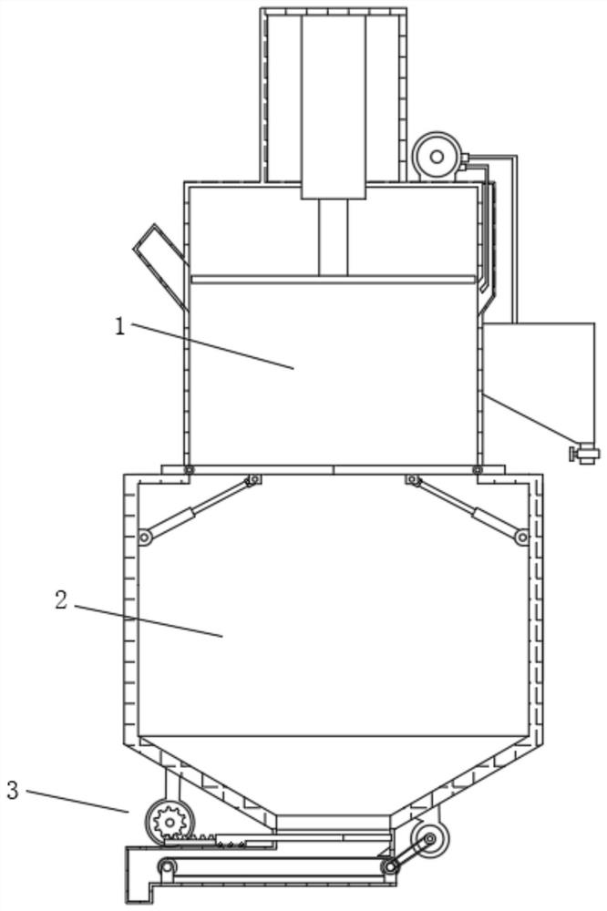
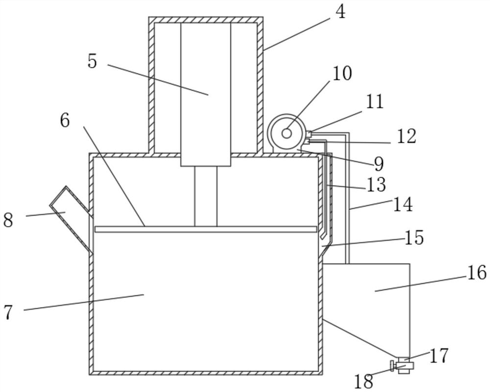
[0022] A kind of sludge collection equipment, in order to solve the problem that sludge carries out secondary pollution to the environment, as a preferred embodiment, such as figure 1 , figure 2 , image 3 with Figure 4 As shown, it includes a static compression chamber 1, a material storage chamber 2 and a transport device 3. The static compression chamber 1 includes a compression chamber 4 and a static chamber 7. The interior of the compression chamber 4 is provided with a hydraulic rod 5, and one end of the hydraulic rod 5 The pressure plate 6 is fixedly connected, the side of the static chamber 7 is provided with a feed port 8 and a pipe chamber 15, one side of the static chamber 7 is fixedly installed with a sewage tank 16, and the top of the static chamber 7 is provided with a water pump fixing frame 9. A water pump 10 is provided inside the water pump fixing frame 9. One end of the water pump 10 is provided with a water suction port 12 and a water outlet 11. The bot...


PUM


Abstract

The invention relates to the technical field of sludge treatment equipment, in particular to sludge collecting equipment. The equipment comprises a standing compression cavity, a material containing cavity and a conveying device, the standing compression cavity comprises a compression cavity and a standing cavity, a hydraulic rod is arranged in the compression cavity, one end of the hydraulic rod is fixedly connected with a pressing plate, the material containing cavity comprises a material containing chamber, and a pressure-bearing material blocking plate is arranged at the top of the material containing chamber; hydraulic rod fixing frames are installed on the side wall of the material containing chamber and the bottom of the pressure-bearing material blocking plate, pushing hydraulic rods and shaft blocking plates are arranged in the hydraulic rod fixing frames, the conveying device comprises a conveying cavity, a first discharging opening is formed in the bottom of the material containing cavity, a material blocking groove is formed in one end of the conveying cavity, and a material blocking plate is arranged in the material blocking groove; a conveying belt fixing frame is arranged in the conveying cavity, and a second discharging cavity is formed in one end of the conveying cavity, so that the problems that secondary pollution is caused, stink is generated, the sludge dewatering effect is poor and the efficiency is low during sludge treatment at present are solved.

Description

technical field [0001] The invention relates to the technical field of sludge treatment equipment, in particular to sludge collection equipment. Background technique [0002] Sludge is the product of sewage treatment, which is an extremely complex heterogeneous body composed of organic debris, bacterial cells, inorganic particles, colloids, etc. The main characteristics of sludge are high water content (up to 99%), high organic matter content, easy to rot and smell, and fine particles, small specific gravity, and colloidal liquid state. It is a thick substance between liquid and solid. It is quite difficult to collect sludge in the industrial process. At present, there are three main methods for separating sludge and water, namely membrane filtration, sedimentation, and centrifugation. Disposal is an important link after sewage treatment. Generally speaking, after the dehydrator separates the sludge, the sludge will reach the conveyor, and the sludge will be transported fro...

Claims


Application Information

Patent Timeline
Patent Type & Authority Applications(China)
IPC IPC(8): C02F11/121
CPCC02F11/121C02F2303/02
Inventor 张小武张寅清李尧唐景春
Owner 新沂市新南环保产业技术研究院有限公司
Learn More