Electronic equipment
A technology for electronic equipment and sub-faces, which is applied in branch equipment, electrical equipment shells/cabinets/drawers, electrical components, etc., and can solve the problems of difficult assembly of shells and appearance parts
- Summary
- Abstract
- Description
- Claims
- Application Information
AI Technical Summary
Problems solved by technology
Method used
Image
Examples
Embodiment 1
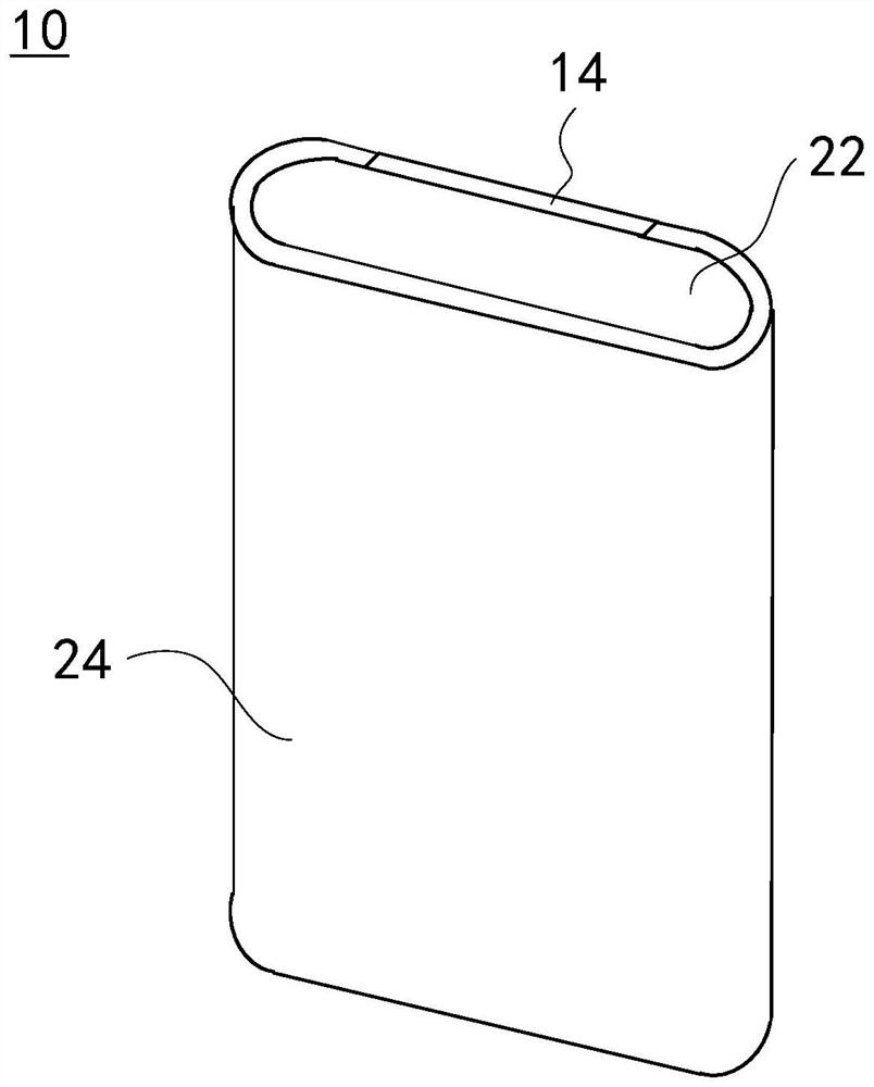
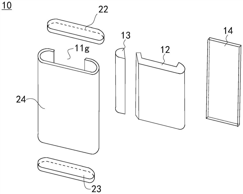
[0079] In the first embodiment, the middle frame is designed as a split structure including the first shell 12 and the second shell 13, so that the first shell 12 and the second shell 13 can be respectively installed into the accommodation of the curved screen module. cavity. This split middle frame design can meet the assembly requirements when the opening 11g between the first side portion 111 and the second side portion 113 in the curved screen module is narrow and the overall width of the middle frame is large, which overcomes the traditional The difficulty of assembling the middle frame and the curved screen module with a large curvature facilitates the realization of a large viewing angle display design of the electronic device 10 .
[0080] like Figure 10 and Figure 11 As shown, in the second embodiment, the difference from the above-mentioned first embodiment is that the first mating surface 12a is protruded with a first snap protrusion 121, and the second mating s...
Embodiment 2
[0083] In the second embodiment, the first casing 12 and the second casing 13 are detachably connected through the engagement of the first locking protrusion 121 and the first locking groove 131, so that the first casing 12 and the second casing 13 can be connected conveniently and reliably. The second shell 13 is fixedly installed in the receiving cavity of the curved screen module.
[0084] In other embodiments, the positions of the first locking protrusions 121 and the first locking grooves 131 can be interchanged, that is, the first locking protrusions 121 are provided on the second mating surface 13 a of the second housing 13 , and the first locking grooves 131 are opened. on the first mating surface 12a of the first housing 12 . The structures of the first latching protrusion 121 and the first latching slot 131 are not limited to the above, but can be designed as required, as long as a detachable connection can be achieved. For example, the first locking protrusion 121 ...
Embodiment 6
[0093] In the sixth embodiment, through the cooperation of the first sub-surface 12a1 and the third sub-surface 13a1, as well as the engagement of the second locking protrusion 123 and the second locking groove 132, the first casing 12 and the second casing 13 can be formed to be compatible. By disassembling and connecting, the first casing 12 and the second casing 13 can be fixedly installed in the receiving cavity of the curved screen module conveniently and reliably.
[0094] In other embodiments, the positions of the second latching protrusions 123 and the second latching grooves 132 can be interchanged, that is, the second latching protrusions 123 are provided on the second mating surface 13 a of the second housing 13 , and the second latching grooves 132 are opened on the first mating surface 12a of the first housing 12 . The structure of the second latching protrusion 123 is not limited to the above, but can be designed as required, as long as a detachable connection ca...
PUM
 Abstract
Description
Claims
Application Information
 - R&D
- Intellectual Property
- Life Sciences
- Materials
- Tech Scout
- Unparalleled Data Quality
- Higher Quality Content
- 60% Fewer Hallucinations
Browse by: Latest US Patents, China's latest patents, Technical Efficacy Thesaurus, Application Domain, Technology Topic, Popular Technical Reports.
© 2025 PatSnap. All rights reserved.Legal|Privacy policy|Modern Slavery Act Transparency Statement|Sitemap|About US| Contact US: help@patsnap.com


