
Double-channel heat dissipation generator

A generator, dual-channel technology, applied in the direction of electromechanical devices, electrical components, electric components, etc., can solve the problems of uneven heat dissipation, unadjustable heat dissipation capacity, cold air interference, etc.

Active Publication Date: 2021-05-18
德阳市产品质量监督检验所
View PDF11 Cites 1 Cited by
  • Summary
  • Abstract
  • Description
  • Claims
  • Application Information

AI Technical Summary

Problems solved by technology

[0004] The purpose of the present invention is to provide a dual-channel heat dissipation generator for the above disadvantages, and to solve the problems of interference of cold air flow, non-adjustable heat dissipation capacity and uneven heat dissipation in the heat dissipation of existing generators.

Method used


Image

  • Double-channel heat dissipation generator
  • Double-channel heat dissipation generator
  • Double-channel heat dissipation generator

Examples


Embodiment 1

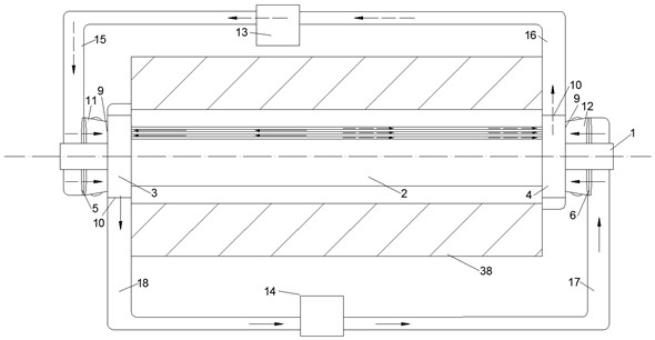
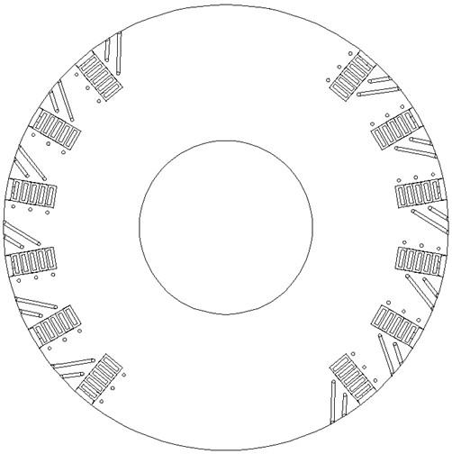
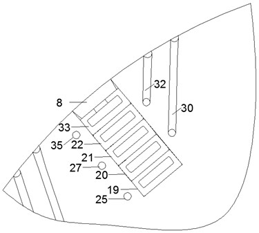
[0027] See attached Figure 1~7 . The dual-channel heat dissipation generator includes a rotating body; the rotating body includes a shaft body 1, an iron core body 2, a winding, a left fixed cover 3, a right fixed cover 4, a left fan 5 and a right fan 6; the shaft body 1 There is an iron core body 2, a left fan 5 and a right fan 6; the iron core body 2 is located between the left fan 5 and the right fan 6; The wire slot 7; the wire is wound on the wire slot 7 of the iron core body 2; the top of the wire slot 7 is provided with a slot stopper 8 for closing the wire slot 7; the left end of the iron core body 2 is covered with a left The fixed cover 3 has a right fixed cover 4 on the right end cover; the left fixed cover 3 and the right fixed cover 4 both include an air inlet end face 9 and an air outlet side 10; The end surface 9 is pressed into the wind flow, and pressed out from the air outlet side 10 of the right fixed cover 4; Side 10 is pressed out. It can be seen from...

Embodiment 2

[0029] See attached Figure 1~7 . The dual-channel heat dissipation generator includes a rotating body; the rotating body includes a shaft body 1, an iron core body 2, a winding, a left fixed cover 3, a right fixed cover 4, a left fan 5 and a right fan 6; the shaft body 1 There is an iron core body 2, a left fan 5 and a right fan 6; the iron core body 2 is located between the left fan 5 and the right fan 6; The wire slot 7; the wire is wound on the wire slot 7 of the iron core body 2; the top of the wire slot 7 is provided with a slot stopper 8 for closing the wire slot 7; the left end of the iron core body 2 is covered with a left The fixed cover 3 has a right fixed cover 4 on the right end cover; the left fixed cover 3 and the right fixed cover 4 both include an air inlet end face 9 and an air outlet side 10; The end surface 9 is pressed into the wind flow, and pressed out from the air outlet side 10 of the right fixed cover 4; Side 10 is pressed out. It can be seen from...

Embodiment 3

[0032] See attached Figure 1~7 . The dual-channel heat dissipation generator includes a rotating body; the rotating body includes a shaft body 1, an iron core body 2, a winding, a left fixed cover 3, a right fixed cover 4, a left fan 5 and a right fan 6; the shaft body 1 There is an iron core body 2, a left fan 5 and a right fan 6; the iron core body 2 is located between the left fan 5 and the right fan 6; The wire slot 7; the wire is wound on the wire slot 7 of the iron core body 2; the top of the wire slot 7 is provided with a slot stopper 8 for closing the wire slot 7; the left end of the iron core body 2 is covered with a left The fixed cover 3 has a right fixed cover 4 on the right end cover; the left fixed cover 3 and the right fixed cover 4 both include an air inlet end face 9 and an air outlet side 10; The end surface 9 is pressed into the wind flow, and pressed out from the air outlet side 10 of the right fixed cover 4; Side 10 is pressed out. It can be seen from...


PUM


Abstract

The invention discloses a double-channel heat dissipation generator, and belongs to the field of generators. An iron core body, a left fan and a right fan are arranged on a shaft body. The iron core body is positioned between the left fan and the right fan; the outer wall of the iron core body is provided with a plurality of axially distributed wire slots; the winding wire is wound on the wire slot of the iron core body; the top of the wire groove is provided with a groove block used for sealing the wire groove. A left fixed cover covers the left end of the iron core body, and a right fixed cover covers the right end of the iron core body; the left fixing cover and the right fixing cover each comprise an air inlet end face and an air outlet side face. The left fan is used for pressing air flow from the air inlet end face of the left fixing cover and pressing the air flow out from the air outlet side face of the right fixing cover; and the right fan is used for pressing air flow from the air inlet end face of the right fixing cover and pressing the air flow out from the air outlet side face of the left fixing cover. According to the double-channel heat dissipation generator, the rotating body is provided with the double channels in the length direction, heat dissipation is not interfered with each other, the heat dissipation capacity is adjustable, heat dissipation of the double channels is complementary, heat dissipation of the rotating body is uniform, and the service life of equipment is long.

Description

technical field [0001] The invention belongs to the technical field of generators, and in particular relates to a dual-channel heat dissipation generator. Background technique [0002] A known principle of a large-scale generator, the winding of the rotating body is wound on the slot of the iron core of the rotating body, and after the winding of the rotating body is connected to direct current, when the rotating body rotates as a whole, a rotating magnetic field is formed . The U, V, and W three-phase windings in the stator core cut the magnetic field in sequence, and induce an electromotive force in the stator windings. [0003] In the existing generator heat dissipation method, after the high-pressure fan of the generator is pressurized, the cold air is combined to ventilate and dissipate heat in the direction parallel to the shaft and perpendicular to the shaft. The air holes are complex and there is interference between the air flows. The wind loss is large. Even so,...

Claims


Application Information

Patent Timeline
IPC IPC(8): H02K1/26H02K1/32H02K3/48H02K9/06H02K3/12H02K3/28H02K1/20H02K9/19
CPCH02K1/20H02K1/265H02K1/32H02K3/12H02K3/28H02K3/487H02K9/06H02K9/19H02K2205/09
Inventor 黄琼王宏达谢东
Owner 德阳市产品质量监督检验所
Learn More