Beam direction adjusting method and device and antenna system

A beam direction and antenna system technology, applied in the fields of devices, beam direction adjustment methods, and antenna systems, can solve problems such as high cost and unfavorable large-scale commercial use

Inactive Publication Date: 2021-05-18
SHANGHAI HUAWEI TECH CO LTD
View PDF5 Cites 3 Cited by
  • Summary
  • Abstract
  • Description
  • Claims
  • Application Information

AI Technical Summary

Problems solved by technology

However, the cost of the second method is relatively high, which is not conducive to large-scale commercial use.

Method used


Image

  • Beam direction adjusting method and device and antenna system
  • Beam direction adjusting method and device and antenna system
  • Beam direction adjusting method and device and antenna system

Examples


Embodiment Construction

[0028] Embodiments of the present application are described below in conjunction with the accompanying drawings. Apparently, the described embodiments are only part of the embodiments of the present invention, not all of them. Those skilled in the art know that, with the emergence of new application scenarios, the technical solutions provided in the embodiments of the present application are also applicable to similar technical problems.

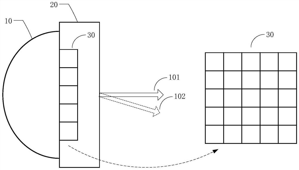
[0029] An embodiment of the present application provides a beam direction adjustment method, the method is applied to an antenna system, the antenna system includes a microwave antenna and a radome installed at the aperture of the microwave antenna, the radome includes M×N liquid crystal units The composed liquid crystal array, when it is detected that the microwave antenna deviates to a certain angle, the transmission phase of the liquid crystal unit can be changed by adjusting the liquid crystal bias of the liquid crystal array in the radom...


PUM


Abstract

The invention discloses a beam direction adjusting method, which is applied to an antenna system comprising a microwave antenna and an antenna housing, the antenna housing comprises a liquid crystal array composed of M*N liquid crystal units, and the method comprises the following steps: obtaining an azimuth angle and / or a pitch angle of the microwave antenna; determining a target scanning angle of the microwave antenna according to the azimuth angle and / or the pitch angle; determining a first bias value of the liquid crystal array according to the target scanning angle; and setting the voltage of the liquid crystal array as a first bias value. The embodiment of the invention further provides a corresponding device. According to the technical scheme, when it is detected that the microwave antenna deviates to a certain angle, the transmission phase of the liquid crystal unit can be changed by adjusting the liquid crystal bias voltage of the liquid crystal array in the antenna housing, so that corresponding phase distribution is achieved, the angle is scanned by the wave beam of the microwave antenna, and automatic tracking alignment is achieved.

Description

technical field [0001] The present application relates to the technical field of communication, and in particular to a beam direction adjustment method, device and antenna system. Background technique [0002] Microwave communication is mainly used in wireless backhaul scenarios. At present, during the installation process of microwave antennas, it is still necessary to manually climb the tower for alignment, and it takes a long time to fine-tune the antenna alignment. Especially for high-gain narrow-beam antennas in the 80GHz (71-76GHz and 81-86GHz) microwave frequency band, alignment is more difficult, and it is also necessary to resist shaking of the tower. On deployed or newly deployed microwave antennas, the beam scanning function needs to be designed to achieve automatic alignment and anti-shaking functions at a certain angle. [0003] There are currently two ways of implementing beam scanning. The first is to realize beam scanning by mechanical rotation, that is, t...

Claims


Application Information

Patent Timeline
Patent Type & Authority Applications(China)
IPC IPC(8): H01Q1/42H01Q3/46
CPCH01Q1/42H01Q3/46H01Q3/44H04B1/38H01Q15/02
Inventor 曾凌杨宁杜明德孙科蔡梦
Owner SHANGHAI HUAWEI TECH CO LTD
Why Eureka
Try Eureka