
Probe card structure

A probe card and probe technology, which is applied in the field of probe card structure, can solve the problems of increasing test time cost, difficulty in meeting testing requirements with probes, and increasing production costs, etc.

Pending Publication Date: 2021-05-18
SHANGHAI HUAHONG GRACE SEMICON MFG CORP
View PDF0 Cites 1 Cited by
  • Summary
  • Abstract
  • Description
  • Claims
  • Application Information

AI Technical Summary

Problems solved by technology

[0004] At present, in some test cases, the probes on the probe card are difficult to meet the detection requirements. If the probe card is remade for each special case, it will not only increase the production cost, but also increase the test time cost.

Method used


Image

  • Probe card structure
  • Probe card structure
  • Probe card structure

Examples


Embodiment Construction

[0025] The technical solutions in this application will be clearly and completely described below in conjunction with the accompanying drawings. Apparently, the described embodiments are part of the embodiments of this application, not all of them. Based on the embodiments in this application, all other embodiments obtained by persons of ordinary skill in the art without making creative efforts belong to the scope of protection of this application.

[0026] In the description of this application, it should be noted that the terms "center", "upper", "lower", "left", "right", "vertical", "horizontal", "inner", "outer" etc. The indicated orientation or positional relationship is based on the orientation or positional relationship shown in the drawings, and is only for the convenience of describing the present application and simplifying the description, rather than indicating or implying that the referred device or element must have a specific orientation, or in a specific orienta...


PUM


Abstract

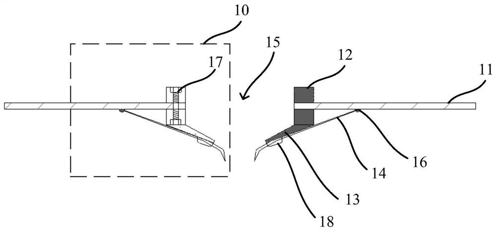
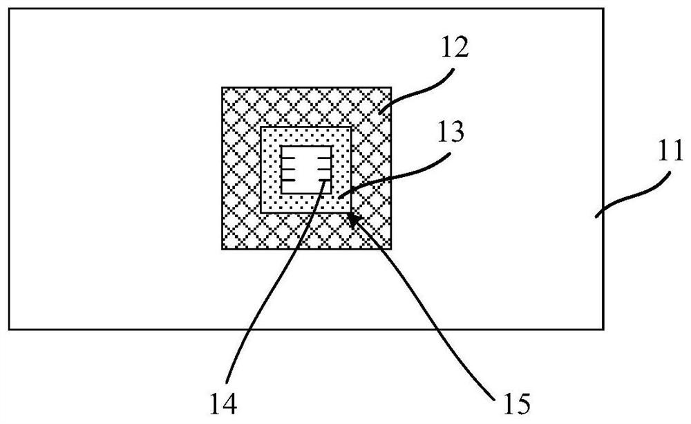
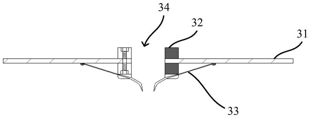
The invention discloses a probe card structure, and relates to the field of integrated circuits. The probe card structure comprises a circuit board, a fixing ring, a probe cantilever bearing ring and a test probe, the circuit board is provided with a detection window, and a test circuit is arranged in the circuit board; the probe cantilever bearing ring is fixed below the circuit board through the fixing ring, and the lower end of the probe cantilever bearing ring is located below the detection window; the top end of the test probe is welded on the back surface of the circuit board, the test probe is connected with the test circuit in the circuit board, and the lower half part of the test probe is fixed at the bottom of the probe cantilever bearing ring; the tip of the test probe is exposed below the detection window; the problem that a detection window on a traditional probe card is small and is difficult to adapt to special detection conditions is solved. When the probe card is used for detecting a chip, a wide operation space and a wide observation field can be provided.

Description

technical field [0001] The present application relates to the field of integrated circuits, in particular to a probe card structure. Background technique [0002] The probe card is the interface between the chip under test and the test equipment in wafer test. The principle of using the probe card is to directly contact the probe on the probe card with the pad or pin of the chip to realize the signal transmission between the test equipment and the chip under test. [0003] Before the wafer leaves the factory, the chip on the wafer is electrically tested through the probe card, which can find the defects of the chip and facilitate the timely improvement of the manufacturing process of the device. Generally, when testing at the wafer level, the probes on the probe card are brought into contact with the test pads of the chip to be tested, and the test equipment sends the test program and receives the test results. [0004] At present, in some test cases, the probes on the pro...

Claims


Application Information

Patent Timeline
Patent Type & Authority Applications(China)
IPC IPC(8): G01R1/073
CPCG01R1/07342
Inventor 张雨田徐嘉良
Owner SHANGHAI HUAHONG GRACE SEMICON MFG CORP
Learn More