Wind power generation device with high conversion efficiency and use method thereof

A technology for wind power generation and conversion efficiency, which is applied to wind power generation, circuit devices, and wind turbines in the same direction as the wind, and can solve problems such as low wind conversion efficiency, low real-time power generation, and internal failures.

Inactive Publication Date: 2021-05-18
天威英利
View PDF0 Cites 2 Cited by
  • Summary
  • Abstract
  • Description
  • Claims
  • Application Information

AI Technical Summary

Problems solved by technology

[0003] However, there are some problems in the use of existing wind power generation devices: 1. The conversion efficiency of wind power is low, and the wind power cannot be fully utilized, resulting in real-time power generation lower than the actual budget. 2. When the wind is strong, it will drive the blades to rotate rapidly. If the speed is too fast, it will easily lead to internal failure and cause danger.

Method used


Image

  • Wind power generation device with high conversion efficiency and use method thereof
  • Wind power generation device with high conversion efficiency and use method thereof
  • Wind power generation device with high conversion efficiency and use method thereof

Examples


Embodiment Construction

[0035]The present invention will be described in detail below with reference to the accompanying drawings to enforce the present specification.

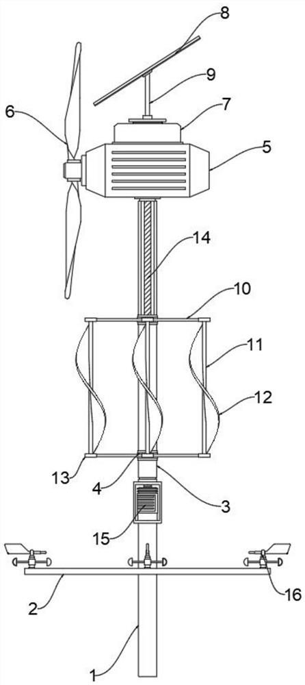
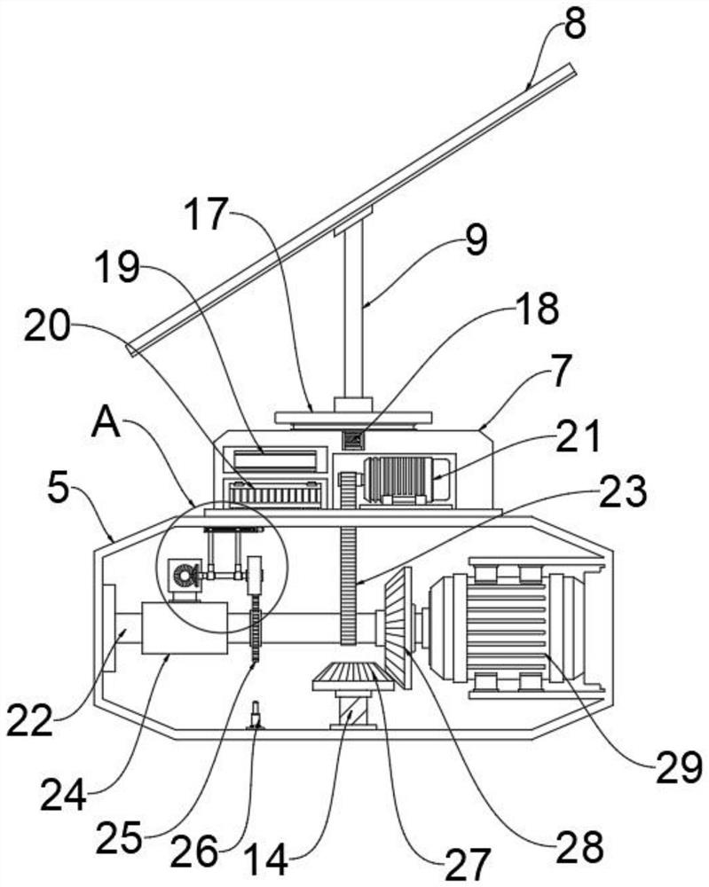
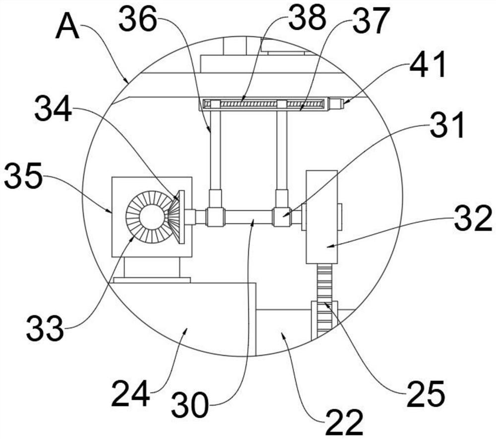
[0036]Such asFigure 1-5As shown, a wind power generation device having a high conversion efficiency, comprising: support column 1, and a rotating column 3 provided on the upper end of the support column 1, and the support column 1 and the rotating column 3 rotate through the damping shaft, support column 1 The upper end of the inside is fixedly installed with the first servo motor 15, and the output shaft of the first servo motor 15 and the rotating column 3 are driven by a coupling;

[0037]The wind power conversion box 5 is mounted on the upper end of the rotating column 3, and the wind power conversion box 5 is fixed to the rotating column 3, and the electric motor 29 is mounted on one side inside the wind power conversion box 5, and the output shaft of the generator 29 is mounted. 22, Moreover, the main shaft 22 is connected to the output sh...


PUM


Abstract

The invention discloses a wind power generation device with high conversion efficiency and a use method thereof. The wind power generation device comprises a supporting column, a rotating column arranged at the upper end of the supporting column, a wind power conversion box, a speed reducer, a wind power auxiliary device and a power box. The wind power conversion box is installed at the upper end of the rotating column, and vertical blades are fixedly installed at the end, located outside the wind power conversion box, of a main shaft; the speed reducer is arranged at the front and rear ends of the main shaft; the wind power auxiliary device is mounted at the lower end outside the rotating column; and the power box is arranged at the upper end of the wind power conversion box, the power box and the wind power conversion box are fixedly welded, and an inverter and a storage battery are installed on one side of the interior of the power box. On one hand, photovoltaic solar energy serves as power to drive a driving motor to conduct auxiliary speed increasing on the main shaft, the stability of the rotating process is ensured on the premise that the conversion efficiency is improved, on the other hand, under cooperation of the wind power auxiliary device, rotating speed compensation is conducted on the main shaft through a first transmission shaft, and the wind power utilization efficiency is further improved.

Description

Technical field[0001]The present invention relates to the field of wind power generation, and more particularly to a wind power generation device having a high conversion efficiency and a method of use.Background technique[0002]The wind is one of the energy that has no public hazard. And it is not exhausted, inexhaustible. For coastal islands, grassland pastoral areas, mountainous areas, grassland pastoral, mountains and plateau, which are well-used, is very suitable for local conditions, which is very suitable for local conditions. Wind power is an important area of ​​renewable energy development. It is an important force to promote the advancement of wind power technology and industrial upgrading. It is an important measure to promote energy structural adjustment. my country's wind energy resources are abundant, speeding up wind power project construction, which is important for promoting regional governance, adjusting energy structure and transformation of economic development. T...

Claims


Application Information

Patent Timeline
IPC IPC(8): F03D9/25F03D1/00F03D3/00F03D3/06F03D7/02F03D15/00H02S20/30H02S10/12H02J7/35
CPCF03D1/00F03D3/005F03D3/061F03D7/0204F03D7/0276F03D9/007F05B2270/101F05B2270/32F05B2270/321F03D9/25F03D15/00H02J7/35H02S10/12H02S20/30Y02E10/56Y02E10/72Y02E10/74Y02E10/76
Inventor 李颖
Owner 天威英利
Why Eureka
Try Eureka