Prestressed full-length anchoring hollow grouting anchor rod with auxetic effect

A technology of full-length anchoring and grouting bolts, applied in the installation of bolts, mining equipment, earth-moving drilling, etc., can solve the problems of long cement mortar consolidation time, reduced normal stress, and slurry leakage.

Active Publication Date: 2021-05-18
SHAOXING UNIVERSITY
View PDF7 Cites 0 Cited by
  • Summary
  • Abstract
  • Description
  • Claims
  • Application Information

AI Technical Summary

Problems solved by technology

This anchoring method is not suitable for formations that require rapid support because the cement mortar has been consolidated for too long and cannot quickly form anchoring force.
In addition, due to the good fluidity of cement slurry, slurry leakage often occurs in broken formations. When grouting upward holes, it is necessary to install multiple supporting devices such as grout stoppers and exhaust pipes. Therefore, the use of such bolts The structure is complex, the construction process is many, and the quality of grouting is not easy to guarantee
[0004] In addition, the above two anchoring methods are anchored through the bonding force between the thread on the surface of the rod body and the anchoring body, and the anchoring force is positively related to the normal stress on the contact surface of the anchor rod-anchor agent. Under the action of axial tension, the section of the rod body will shrink to varying degrees, thereby reducing the normal stress acting on the contact surface of the anchor rod-anchor agent, and finally affecting the shear strength between the anchor rod and the anchoring body

Method used


Image

  • Prestressed full-length anchoring hollow grouting anchor rod with auxetic effect
  • Prestressed full-length anchoring hollow grouting anchor rod with auxetic effect
  • Prestressed full-length anchoring hollow grouting anchor rod with auxetic effect

Examples


Embodiment Construction

[0027] The present invention will be further described below in conjunction with accompanying drawing.

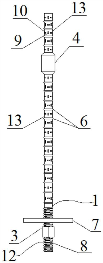
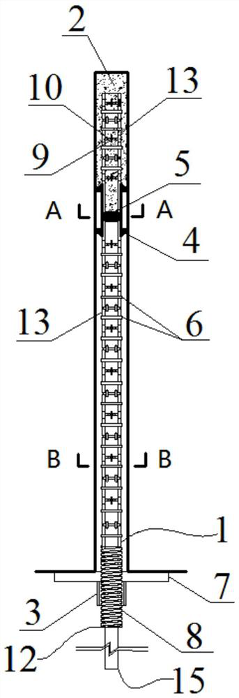
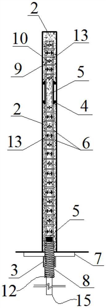
[0028] Such as Figure 1 to Figure 10 As shown, a prestressed full-length anchoring hollow grouting anchor with auxetic effect, including a rod body 12, a tray 7, a nut 3 and a centering ring 4;

[0029] The inside of the rod body 12 is provided with an axially through central grouting hole 14; the rod body 12 is composed of a threaded section 8 at the end and a main body section 1 outside the threaded section 8; the outside of the threaded section 8 is provided with External threads; the surface of the main body section 1 is uniformly fixedly connected with a plurality of protruding rib rings 6 along the length direction, and the part between adjacent protruding rib rings 6 forms a communication part 13; the protruding rib rings 6 The outer diameter is smaller than the diameter of the borehole to be constructed; each connecting portion 13 is provided with a plurality of a...


PUM


Abstract

The invention discloses a prestressed full-length anchoring hollow grouting anchor rod with an auxetic effect. An axial through center grouting hole is formed inside a rod body; the rod body consists of a threaded section located at the tail end and a main body section located outside the threaded section; external screw threads are arranged outside the threaded section; a plurality of protruding rib rings are uniformly and fixedly connected to the surface of the main body section in the length direction; a communicating part is formed by a part between the adjacent protruding rib rings; the outer diameter of the protruding rib rings is smaller than the hole diameter of a to-be-constructed drill hole; a plurality of axial flat holes and a plurality of annular flat holes which communicate with a center grouting hole are formed in each communicating part; a tray is slidably sleeved on the outer side of the threaded section; a screw nut is connected to the outer side of the threaded section in a threaded fit mode and is closer to the tail end of the rod body than the tray; a centering ring is sleeved outside the main body section; and the outer diameter of the centering ring is matched with the hole diameter of the to-be-constructed drill hole. The anchor rod achieves the auxetic effect, can apply great prestress, and is beneficial to achieving full-length anchoring.

Description

technical field [0001] The invention belongs to the technical field of engineering support, in particular to a prestressed full-length anchoring hollow grouting anchor rod with auxetic effect. Background technique [0002] Because the bolt support can effectively mobilize the self-bearing capacity of the surrounding rock, it can not only support the surrounding rock, but also modify and strengthen the surrounding rock. Therefore, it has been widely used since its birth. It is used in the support of mines, tunnels, slopes, water conservancy and other projects. At present, the widely used bolt support methods can be mainly divided into two categories. One is the first-filled and then-anchored anchor represented by solid threaded steel anchors and resin coils. It has the advantages of high strength and timely support, but because the curing effect of the resin drug coil used is related to whether the stirring and mixing are sufficient, the quality of resin curing is difficult ...

Claims


Application Information

Patent Timeline
IPC IPC(8): E21D21/00E21D20/02E21D20/00
CPCE21D21/0026E21D21/0093E21D20/028E21D20/025E21D20/00
Inventor 薛飞朱振宇蔡瑞金王天佐犹小波朱毅超顾旭东
Owner SHAOXING UNIVERSITY
Why Eureka
Try Eureka