
Tunnel wall cleaning device

A technology for cleaning devices and tunnel walls, which can be used in road cleaning, cleaning methods, construction, etc., and can solve problems that cannot be used to clean electrical equipment installation areas

Pending Publication Date: 2021-05-18
CRCC HIGH TECH EQUIP CORP LTD
View PDF1 Cites 1 Cited by
  • Summary
  • Abstract
  • Description
  • Claims
  • Application Information

AI Technical Summary

Problems solved by technology

The tunnel wall cleaning device provided by the present invention adopts the dry ice cleaning method, which can clean the railway tunnel wall, and is especially suitable for cleaning the installation area of ​​electrical equipment on the subway tunnel wall, and solves the problem that the water washing method in the prior art cannot be used to clean electrical equipment Problems with the installation area

Method used


Image

  • Tunnel wall cleaning device
  • Tunnel wall cleaning device
  • Tunnel wall cleaning device

Examples


Embodiment 1

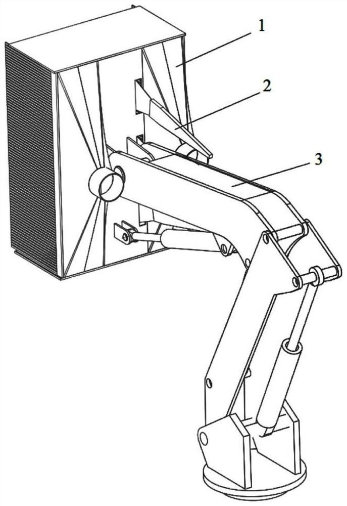
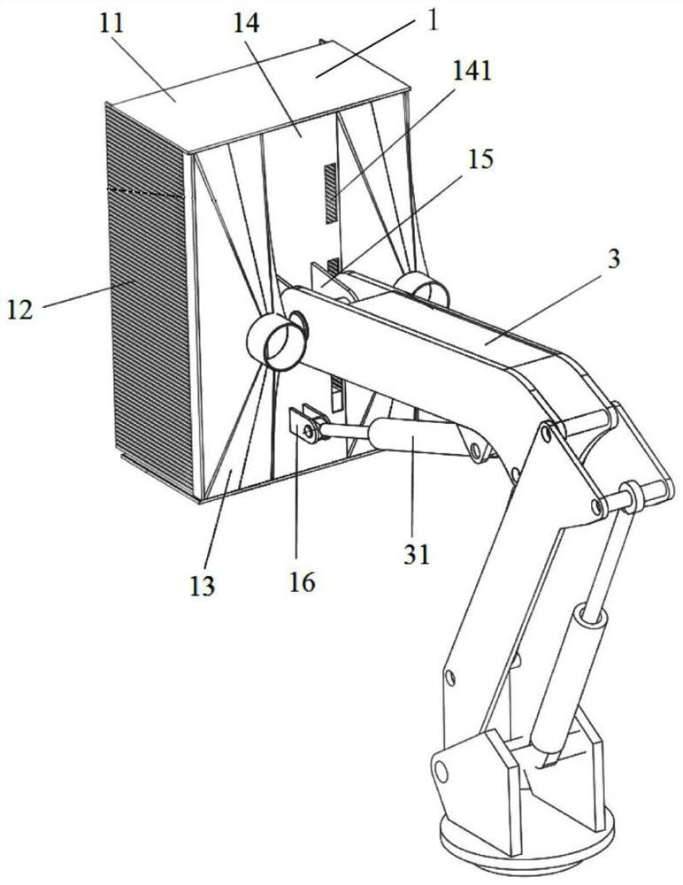
[0036] Such as figure 1Shown is a schematic structural view of the tunnel wall cleaning device according to the present invention. The tunnel wall cleaning device of the present invention includes a dry ice blasting assembly 2 , the dry ice blasting assembly 2 is fixedly connected to a cover body 1 , and a mechanical arm 3 is connected to the back of the cover body. Setting the cover body 1 can prevent dust from being raised in the cleaning area during cleaning; the cover body 1 is provided with a brush discharge plate 12 when cleaning the electrical equipment installation area on the tunnel wall, the bristles on the brush discharge plate 12 can realize the cleaning function on the one hand, On the other hand, it can avoid obstacles. This design enables the cover body 1 to be as close to the tunnel wall as possible through the mechanical arm 3 during cleaning operations to prevent dust, which solves the problem of high-pressure wind cleaning in the prior art. No matter what t...

Embodiment 2

[0052] last read Figure 5 , Figure 6 Shown is a schematic structural view of the second embodiment of the tunnel wall cleaning device according to the present invention.

[0053] Implement two on the basis of embodiment one and be provided with two slide plates 17 on the outside of brush plate 12, each slide plate 17 is connected with a regulating oil cylinder 4, and the upper and lower sides of each slide plate 17 are connected with guide mechanism The baffle 11 is connected.

[0054] In this embodiment, the guide mechanism includes guide grooves 111 and rollers 112; guide grooves 111 are formed on the left and right edges of the side of the baffle plate 11 opposite to the brush discharge plate 12, and rollers are installed in the guide grooves 111. 112 , the sliding plate 17 moves back and forth along the bristle direction of the brush removal plate 12 under the action of the adjustment oil cylinder 4 and the roller 112 , thereby adjusting the length of the bristles actu...


PUM


Abstract

The invention relates to a tunnel wall cleaning device which comprises a dry ice spraying assembly (2), the dry ice spraying assembly (2) is fixedly connected to a cover body (1), and the back of the cover body is connected with a mechanical arm (3). The cover body (1) can prevent dust from flying in a cleaning area during cleaning; a row brush plate (12) is arranged on the cover body (1), when an electrical equipment installation area on the tunnel wall is cleaned, bristles on the row brush plate (12) can achieve a sweeping function and can avoid obstacles; through the design, the cover body (1) can be close to the tunnel wall face as much as possible through the mechanical arm (3) in the cleaning process, and dust raising is prevented. The problem that in the prior art, a high-pressure air blowing cleaning mode is large in dust raising amount is solved.

Description

technical field [0001] The invention relates to the technical field of railway maintenance machinery, in particular to a tunnel wall cleaning device. Background technique [0002] After the construction of the subway tunnel is completed, as the operation time increases, dust pollution and dust accumulation will occur to varying degrees on the top, sides, track bed and trackside equipment of the tunnel wall. In particular, due to the complex structure of the tunnel side walls, cables and equipment, the lack of cleaning and dust accumulation is becoming more and more serious. Long-term accumulation of dust will lead to failure of electrical equipment, such as local short circuit, leakage, and various failures caused by poor heat dissipation of heating elements. Since the dust on the tunnel wall and electrical equipment is very harmful to the safe operation of electrical equipment, the subway tunnel wall, especially the parts where electrical equipment and protruding cable rac...

Claims


Application Information

Patent Timeline
Patent Type & Authority Applications(China)
IPC IPC(8): E01H1/00E01H1/08
CPCE01H1/005E01H1/0845
Inventor 卫明赵强
Owner CRCC HIGH TECH EQUIP CORP LTD
Learn More