


Quick Research
Generate reliable direction feasibility study reports for your R&D in just a few steps.

Technical Q&A
Discover and master advanced knowledge NOW. Basics, ideas, possibilities, all at once.

Find Solutions
As an expert in R&D theories, this can generate solutions to your technical problems instantly.

Evaluate Feasibility
Analyze your overall solution with one click, know your potential R&D risks in advance.

Monitor Landscape
Get weekly tech updates, stay abreast of the latest tech innovations and key insights.
Municipal road surface cutting equipment
A cutting equipment and municipal technology, which is applied in the municipal field, can solve the problems that the blade cannot cut quickly, the asphalt melts, etc.
- Summary
- Abstract
- Description
- Claims
- Application Information
AI Technical Summary
Problems solved by technology
Method used
Image

Examples
Embodiment 1
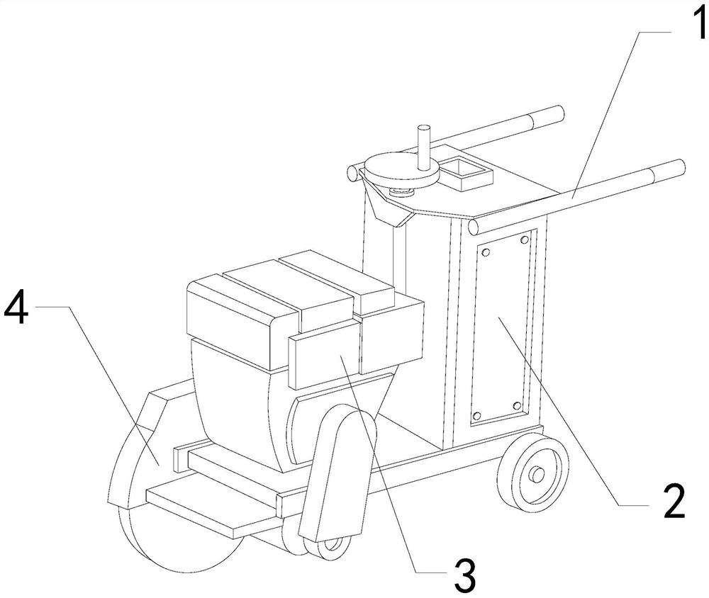
[0026] For example figure 1 -example Figure 5 Shown:
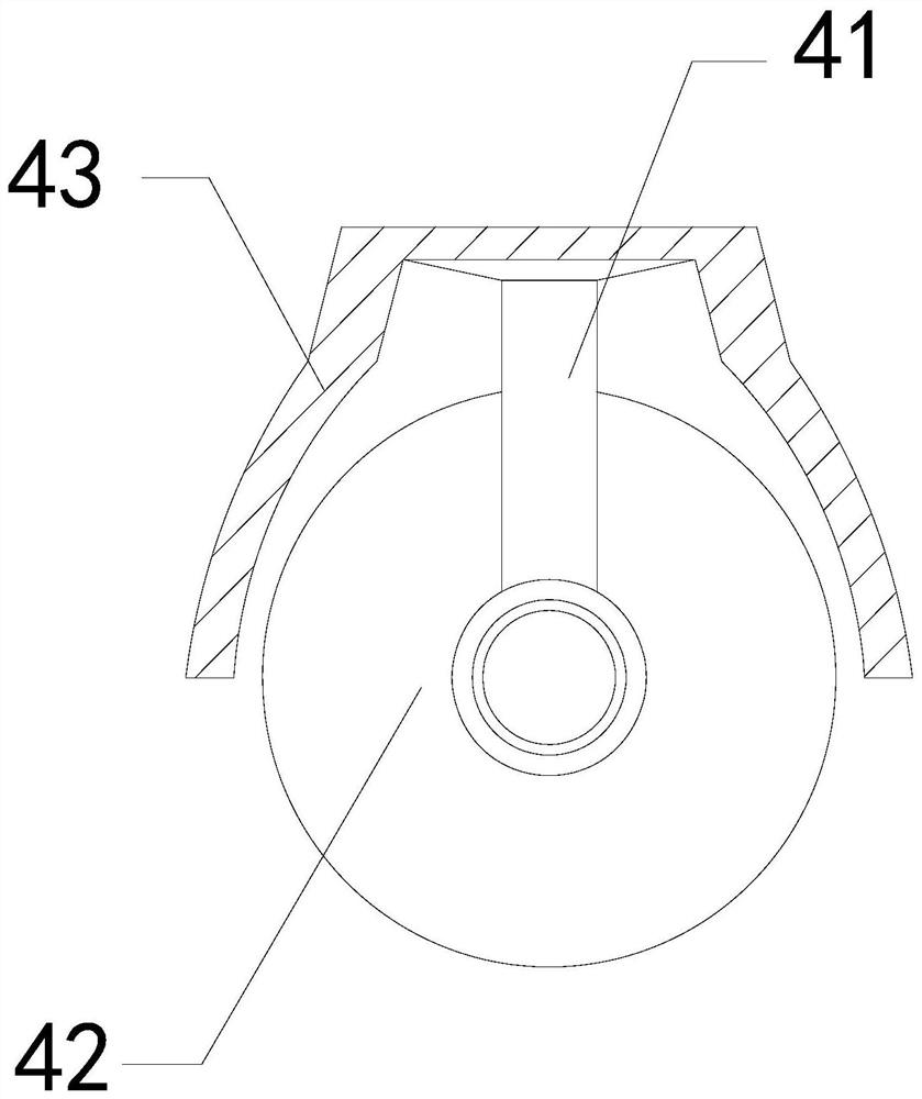
[0027] The present invention provides a road surface cutting equipment for municipal use, the structure of which includes a handrail 1, a body 2, a driver 3, and a cutting tool 4, the handrail 1 is welded to the upper end of the body 2, and the driver 3 is embedded on the top The surface position, the cutting tool 4 is installed on the left side of the driver 3; the cutting tool 4 includes a support frame 41, a blade 42, and a protective cover 43, and the support frame 41 is embedded in the top position of the inner wall of the protective cover 43, The blade 42 is movably engaged with the bottom of the support frame 41 .
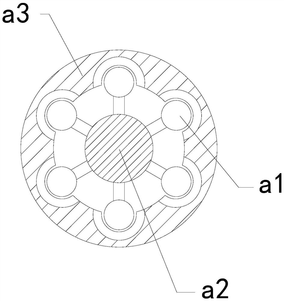
[0028] Wherein, the blade 42 includes a vibration mechanism a1, a built-in block a2, and a combination ring a3, the vibration mechanism a1 and the built-in block a2 are an integrated structure, the built-in block a2 is installed at the inner center of the combination ring a3, and the The inner side o...
Embodiment 2
[0034] For example Image 6 -example Figure 8 Shown:
[0035] Wherein, the combination ring a3 includes a heat sink c1, a frame body c2, an inner frame c3, and a contact-increasing cavity c4, the heat sink c1 is fixed on the inner side of the contact-increasing cavity c4, and the inner frame c3 and the frame body c2 are In an integrated structure, the contact-increasing chamber c4 is embedded in the inner position of the frame body c2. There are six contact-increasing chambers c4, which are evenly distributed in a circular shape on the frame body c2. The heat sink c1 can enhance the contact between the object and the The contact area with the outside world can accelerate the heat dissipation rate of the object.
[0036] Wherein, the inner frame c3 includes an connecting plate c31, a heat conducting strip c32, an elastic piece c33, and a bottom plate c34, the connecting plate c31 is connected to the upper end of the bottom plate c34 through the elastic piece c33, and the hea...
PUM
 Abstract
Description
Claims
Application Information
 - R&D Engineer
- R&D Manager
- IP Professional
- Industry Leading Data Capabilities
- Powerful AI technology
- Patent DNA Extraction
Browse by: Latest US Patents, China's latest patents, Technical Efficacy Thesaurus, Application Domain, Technology Topic, Popular Technical Reports.
© 2024 PatSnap. All rights reserved.Legal|Privacy policy|Modern Slavery Act Transparency Statement|Sitemap|About US| Contact US: help@patsnap.com