Laser marking machine with defective product detection and classification structure
A technology of laser marking machine and classification structure, which is applied in sorting and other directions, can solve the problems of lack of detection and classification of defective products, and achieve the effect of convenient compaction and enhanced detection accuracy
- Summary
- Abstract
- Description
- Claims
- Application Information
AI Technical Summary
Problems solved by technology
Method used
Image

Examples
Embodiment 1
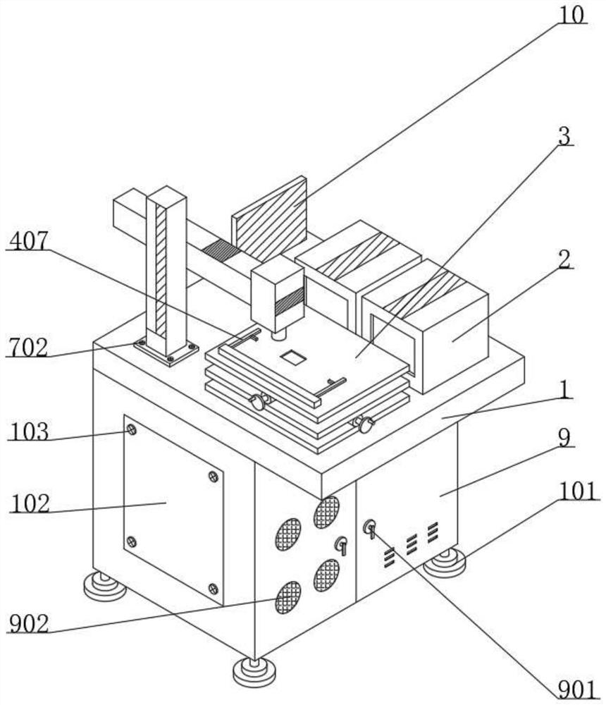
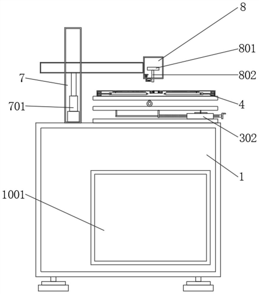
[0032] Example 1: See figure 1 and figure 2, a laser marking machine with a defective product detection and classification structure, including a base 1, a collection box 2 and a support plate 3, the function of the base 1 is to provide support for the device, the function of the collection box 2 is to facilitate the collection of materials, and the support plate The role of 3 is to provide support for the first sleeve 302, the top of the base 1 is installed with the collection box 2, the top of the base 1 is installed with the support plate 3, the top of the support plate 3 is installed with the first pillar 4, and the top of the first pillar 4 The function is to provide support for the second motor 401. The top of the support plate 3 is provided with a bayonet 5. The function of the bayonet 5 is to facilitate the clamping of materials. The top of the base 1 is installed with a second pillar 7. The function of the second pillar 7 It is to provide support for the support box...
Embodiment 2
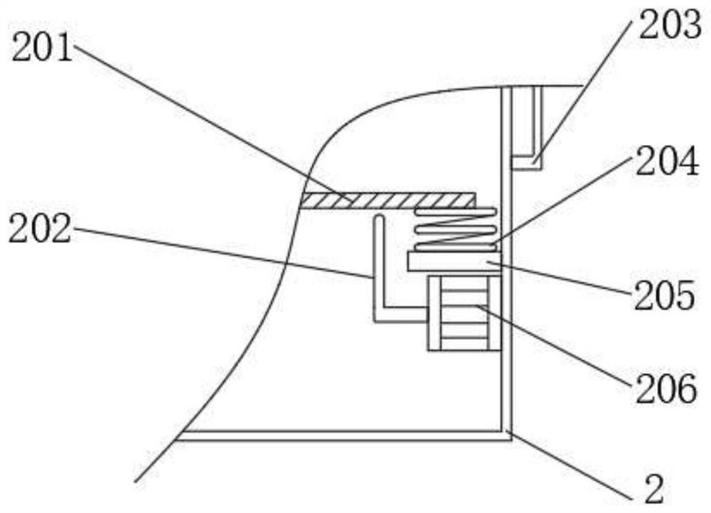
[0033] Example 2: See image 3 , Figure 5 and Figure 6 A first handle 203 is installed on the outer wall of the collection box 2, a first pole 205 is installed on the inner wall of the collection box 2, a first spring 204 is installed on the outer wall of the first pole 205, and a filter screen 201 is installed on one end of the first spring 204 , the inner wall of the collecting box 2 is equipped with a first motor 206, the output end of the first motor 206 is equipped with a cam 202, the inner wall of the first pillar 4 is equipped with a second motor 401, and the output end of the second motor 401 is equipped with a threaded rod 403 , the outer wall of the threaded rod 403 is equipped with a second sleeve 405, the outer wall of the second sleeve 405 is equipped with a first telescopic rod 402, the output end of the first telescopic rod 402 is equipped with a fourth pole 407, the second sleeve 405 The outer wall of the pulley 406 is equipped with a pulley 406, the outer ...
Embodiment 3
[0034] Example 3: See Figure 4 and Figure 7 A first sleeve 302 is installed on the top of the support plate 3, a screw 304 is installed on the inner wall of the first sleeve 302, a handle 303 is installed on one end of the screw 304, and a third pole 301 is installed on one end of the screw 304 through a bearing, The outer wall of the first sleeve 302 is equipped with a connecting channel, the inner wall of the bayonet socket 5 is equipped with a coil 502, the inner wall of the coil 502 is equipped with a second spring 501, and one end of the second spring 501 is equipped with a pressure head 503. The effect of the coil 502 is To facilitate the movement of the second spring 501, the function of the pressure head 503 is to facilitate the compression of materials, the function of the first sleeve 302 is to provide support for the screw 304, the function of the connecting channel is to facilitate the movement of the support plate 3, and the rotation of the handle 303 drives Th...
PUM
 Abstract
Description
Claims
Application Information
 - R&D
- Intellectual Property
- Life Sciences
- Materials
- Tech Scout
- Unparalleled Data Quality
- Higher Quality Content
- 60% Fewer Hallucinations
Browse by: Latest US Patents, China's latest patents, Technical Efficacy Thesaurus, Application Domain, Technology Topic, Popular Technical Reports.
© 2025 PatSnap. All rights reserved.Legal|Privacy policy|Modern Slavery Act Transparency Statement|Sitemap|About US| Contact US: help@patsnap.com