
Method for drilling on curved surface structure

A technology of curved surface structure and to-be-drilled, applied in the field of mechanical processing equipment, can solve problems such as theoretical errors, inability to judge whether the measurement points belong to the same part, inability to timely find out quality problems in the drilling process, etc.

Active Publication Date: 2021-05-18
AVIC BEIJING AERONAUTICAL MFG TECH RES INST
View PDF8 Cites 0 Cited by
  • Summary
  • Abstract
  • Description
  • Claims
  • Application Information

AI Technical Summary

Problems solved by technology

Near the edge of the part, the measurement point of some sensors is likely to exceed the edge of the part, the actual measured point does not belong to the part, and it is impossible to judge whether the measurement point belongs to the same part, resulting in a large deviation
[0009] (2) Assuming the surface equation form may bring theoretical errors
[0010] The surfaces of some parts (for example, some parts that meet the requirements of aircraft aerodynamic shape) are free-form surfaces and cannot be expressed by equations. Even if the surface equations are more complex, they can only be approximate expressions. This simplified approximate expression brings theoretical error
[0011] (3) Constructing complex surface equations will introduce more problems
It is difficult to effectively identify and eliminate motion errors, and it has not been effectively solved so far
[0017] (4) It can only be used to estimate the normal direction of the drilling point, but cannot detect the diameter, position and direction of the hole, does not have the function of on-machine detection, and the function of the detection instrument is not fully utilized
Usually, after drilling in batches, the position and direction of the holes must be measured uniformly with measuring equipment or measuring tools, and the quality problems in the drilling process cannot be found in time, and the processing parameters cannot be adjusted in time according to the quality change trend. During the drilling process, once the position or direction of a hole is out of tolerance, the entire part will become a waste product, resulting in wasted efforts and a large waste
For small parts that can be disassembled and easy to measure, the position and direction of the hole can be measured by testing equipment such as a three-coordinate measuring machine. The processing cycle is shortened and the processing efficiency is reduced; for parts that are not allowed to be disassembled or large parts, testing equipment such as three-coordinate measuring machines cannot be used, and measuring instruments must be used for manual measurement. The measurement results are affected by factors such as worker experience and working status , it is easy to cause misjudgment, if the release is out of tolerance, there will be hidden dangers, and if the qualified product is abandoned, it will cause waste

Method used


Image

  • Method for drilling on curved surface structure
  • Method for drilling on curved surface structure
  • Method for drilling on curved surface structure

Examples


Embodiment Construction

[0051] Embodiments of the present invention will be further described in detail below in conjunction with the accompanying drawings and examples. The detailed description and accompanying drawings of the following embodiments are used to illustrate the principles of the present invention, but cannot be used to limit the scope of the present invention, that is, the present invention is not limited to the described embodiments, without departing from the spirit of the present invention Any modification, substitution and improvement of parts, components and connection methods are covered under.

[0052] It should be noted that, in the case of no conflict, the embodiments in the present application and the features in the embodiments can be combined with each other. The present application will be described in detail below with reference to the accompanying drawings and embodiments.

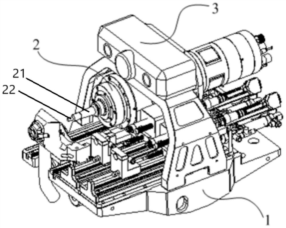
[0053] figure 2 It is a schematic structural view of the drilling equipment of the present inv...


PUM


Abstract

The invention relates to a method for drilling on a curved surface structure. Drilling equipment is used for drilling on the curved surface structure of an object to be drilled, the drilling equipment comprises a motion platform with multiple degrees of freedom and a drilling assembly connected with the motion platform, and the drilling assembly comprises a machine base unit, a drilling unit and a visual detection unit; the machine base unit is installed on the motion platform; the drilling unit is arranged on the machine base unit in a sliding mode and the visual detection unit is fixedly connected to the machine base unit. The method comprises the following steps that firstly, the visual detection unit is aligned with a drilling area of the object to be drilled, and a normal direction of a position to be drilled in the drilling area is calculated; secondly, the position of the drilling unit is adjusted, and the axis of a drilling main shaft arranged on the drilling unit coincides with the normal direction; and thirdly, the drilling main shaft is driven to rotate and move forwards at a high speed, and a target hole is obtained after drilling is completed. The normal direction of the drilling position is obtained through visual detection technology and coincides with the axis of the drilling unit, and the drilling direction precision of the curved surface structure can be improved.

Description

technical field [0001] The invention relates to the field of machining equipment, in particular to a method for drilling holes on curved surface structures. Background technique [0002] When drilling a hole on a curved surface structure, it is necessary to strictly control the angle between the axis of the hole and the curved surface. Therefore, the normal direction at the drilling position of the surface structure must be accurately measured first, and on this basis, the position and direction of the drilling tool can be accurately adjusted to better control the direction of the hole. It can be seen that the accurate measurement of the normal direction at the drilling position of the curved surface structure is a prerequisite. At present, the indirect measurement method is generally used to measure the normal direction of the surface structure, and multiple distance measuring sensors (such as laser distance measuring sensors, etc.) or displacement sensors (such as length ...

Claims


Application Information

Patent Timeline
IPC IPC(8): B23B35/00
CPCB23B35/00
Inventor 杜兆才薛俊姚艳彬荆道艳
Owner AVIC BEIJING AERONAUTICAL MFG TECH RES INST
Learn More