Device for copper recovery and skin opening of cables of different specifications
A technology of cables and specifications, applied in electronic waste recycling, recycling technology, circuits, etc., can solve the problems of high labor intensity, slow speed of cable peeling and copper extraction, hand injury, etc.
- Summary
- Abstract
- Description
- Claims
- Application Information
AI Technical Summary
Problems solved by technology
Method used
Image
Examples
Embodiment 1
[0072] A device for copper recovery and peeling of cables with different specifications, such as figure 1 As shown, it includes a first fixed plate 1, a second fixed plate 2, a third fixed plate 3, a peeling mechanism 4, a progressive mechanism 5 and a clamping mechanism 6, and the first fixed plate 1 on the left and right sides is provided with There is a second fixed plate 2, a third fixed plate 3 is provided on the front and rear sides in the middle of the second fixed plate 2, a peeling mechanism 4 is provided on the top left side of the second fixed plate 2, and a skin opening mechanism 4 is provided on the top left side of the second fixed plate 2. The progressive mechanism 5 is provided with a clamping mechanism 6 between the tops of the two third fixing plates 3 .
[0073] When people need to recover the copper in the cable, they can use this device for copper recovery and peeling of cables with different specifications. First, people need to put the cable into the adv...
Embodiment 2
[0075] On the basis of Example 1, such as Figure 2-Figure 4 As shown, the peeling mechanism 4 includes a fourth fixing plate 41, a first fixing frame 42, a first rotating shaft 43, a second rotating shaft 44, a cutter 45 and a first fixing sleeve 46, and the left rear side of the second fixing plate 2 The top is provided with a fourth fixed plate 41, the top of the left front side of the second fixed plate 2 is provided with a first fixed frame 42, the upper side of the fourth fixed plate 41 is rotatably provided with a first rotating shaft 43, the fourth fixed plate 41 and the first A second rotating shaft 44 is rotatably provided between the upper side of the fixed frame 42, and a first fixed sleeve 46 is rotatably provided between the front side of the second rotating shaft 44 and the front side of the first rotating shaft 43, and the middle of the first rotating shaft 43 A cutter 45 is arranged between the second rotating shaft 44 and the second rotating shaft 44 .
[00...
Embodiment 3
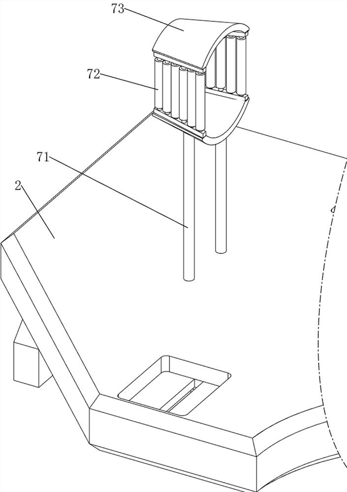
[0082] On the basis of Example 2, such as Figure 5-Figure 8 As shown, a guide mechanism 7 is also included, and the guide mechanism 7 includes a third fixed mount 71, a guide wheel 72 and a guide ring 73, and the top of the left side of the second fixed plate 2 is provided with two third fixed mounts 71 at intervals, two A guide ring 73 is arranged between the top of the third fixing frame 71 , and guide wheels 72 are evenly arranged in the middle of the front and rear sides of the guide ring 73 .
[0083] When the cable is delivered to the guide ring 73, the cable can be sent between the two cutters 45 through the guide wheels 72 on both sides, and the cable is in contact with the guide wheels 72, so that the guide wheels 72 rotate to play a guiding role. Prevent the cable from tilting to the side when it is delivered, and achieve the effect of guiding.
[0084] Also comprise power mechanism 8, power mechanism 8 includes the 4th fixed mount 81, motor 82, spur gear 83 and pu...
PUM
 Abstract
Description
Claims
Application Information
 - R&D
- Intellectual Property
- Life Sciences
- Materials
- Tech Scout
- Unparalleled Data Quality
- Higher Quality Content
- 60% Fewer Hallucinations
Browse by: Latest US Patents, China's latest patents, Technical Efficacy Thesaurus, Application Domain, Technology Topic, Popular Technical Reports.
© 2025 PatSnap. All rights reserved.Legal|Privacy policy|Modern Slavery Act Transparency Statement|Sitemap|About US| Contact US: help@patsnap.com


