


Quick Research
Generate reliable direction feasibility study reports for your R&D in just a few steps.

Technical Q&A
Discover and master advanced knowledge NOW. Basics, ideas, possibilities, all at once.

Find Solutions
As an expert in R&D theories, this can generate solutions to your technical problems instantly.

Evaluate Feasibility
Analyze your overall solution with one click, know your potential R&D risks in advance.

Monitor Landscape
Get weekly tech updates, stay abreast of the latest tech innovations and key insights.
Differential pressure indicator for controlling temperature by using liquid metal
A technology for controlling temperature and liquid metal. It is used in instruments, alarms, springs/shock absorbers, etc. It can solve the problems of false alarms, high rejection rate, time-consuming and labor-intensive, etc., to facilitate temperature control, avoid false alarms, and be easy to use. Effect
- Summary
- Abstract
- Description
- Claims
- Application Information
AI Technical Summary
Problems solved by technology
Method used
Image

Examples
Embodiment 1
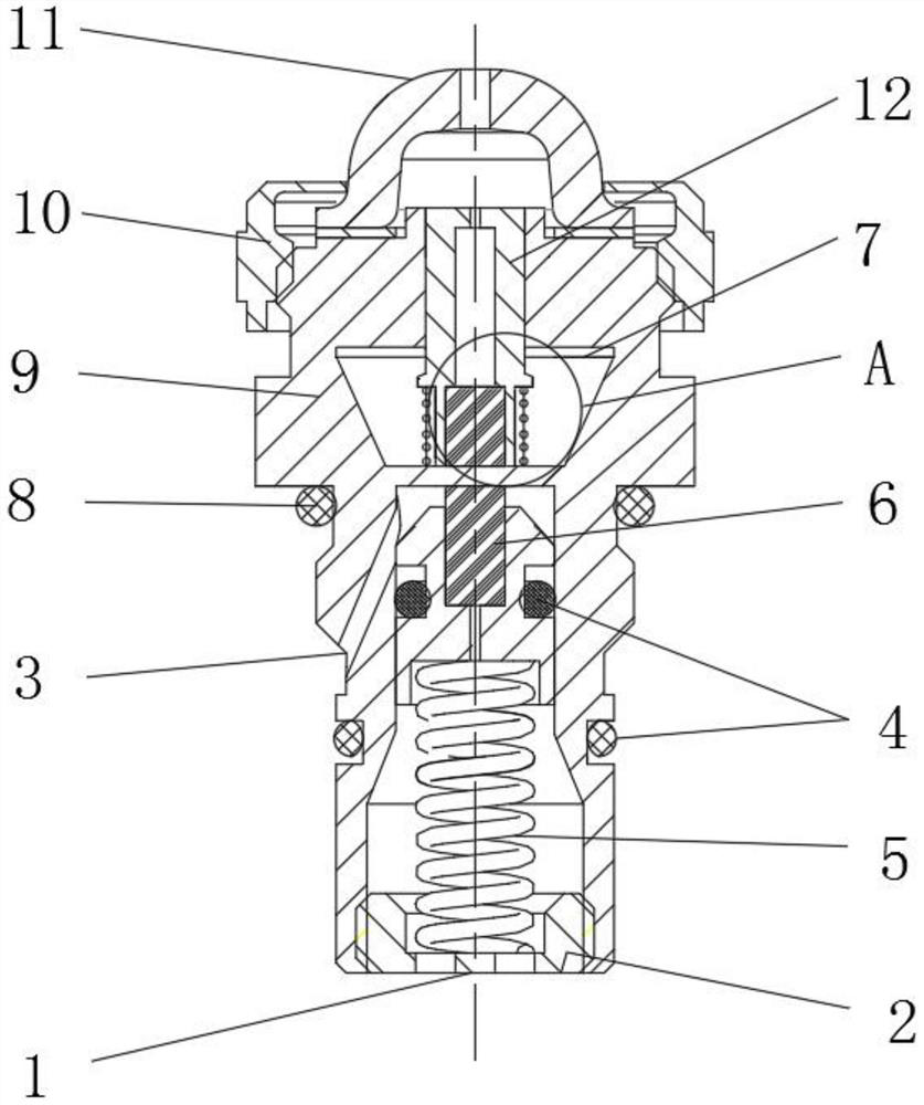
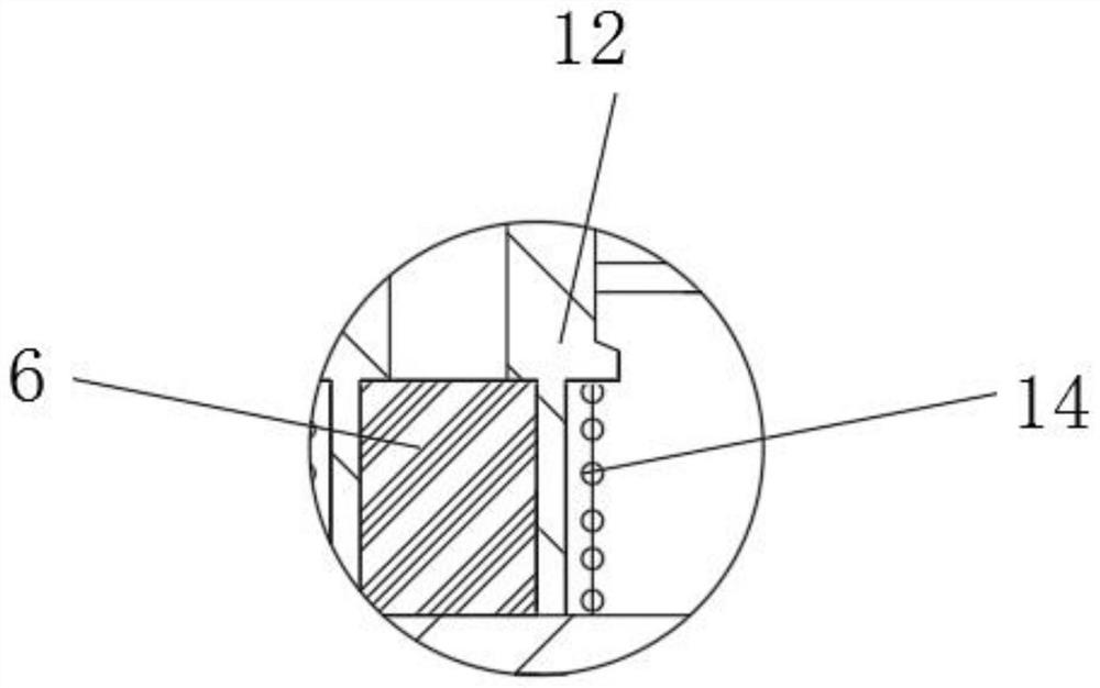
[0025] A differential pressure transmitter that uses liquid metal to control temperature, such as Figure 1-2 As shown, it includes a housing 9, the lower part of the housing 9 and the middle part of the lower end of the housing 9 are respectively provided with a filter oil inlet 3 and a filter oil outlet 1, and the lower end of the housing 9 is fixedly installed with a spring seat 2, a spring seat 2 The lower spring 5 is fixedly installed on the upper part, the lower magnetic steel assembly 6 is fixedly installed on the upper end of the lower spring 5, the upper cavity 7 is opened inside the housing 9, the upper magnetic steel assembly 12 is arranged inside the upper cavity 7, and the upper end of the housing 9 is arranged There is a nut 10, the middle part of the nut 10 is provided with a transparent cover 11, the middle part of the lower magnetic steel assembly 6 and the lower part of the outer surface of the housing 9 are provided with a No. 1 sealing ring 4, and the middle...
Embodiment 2
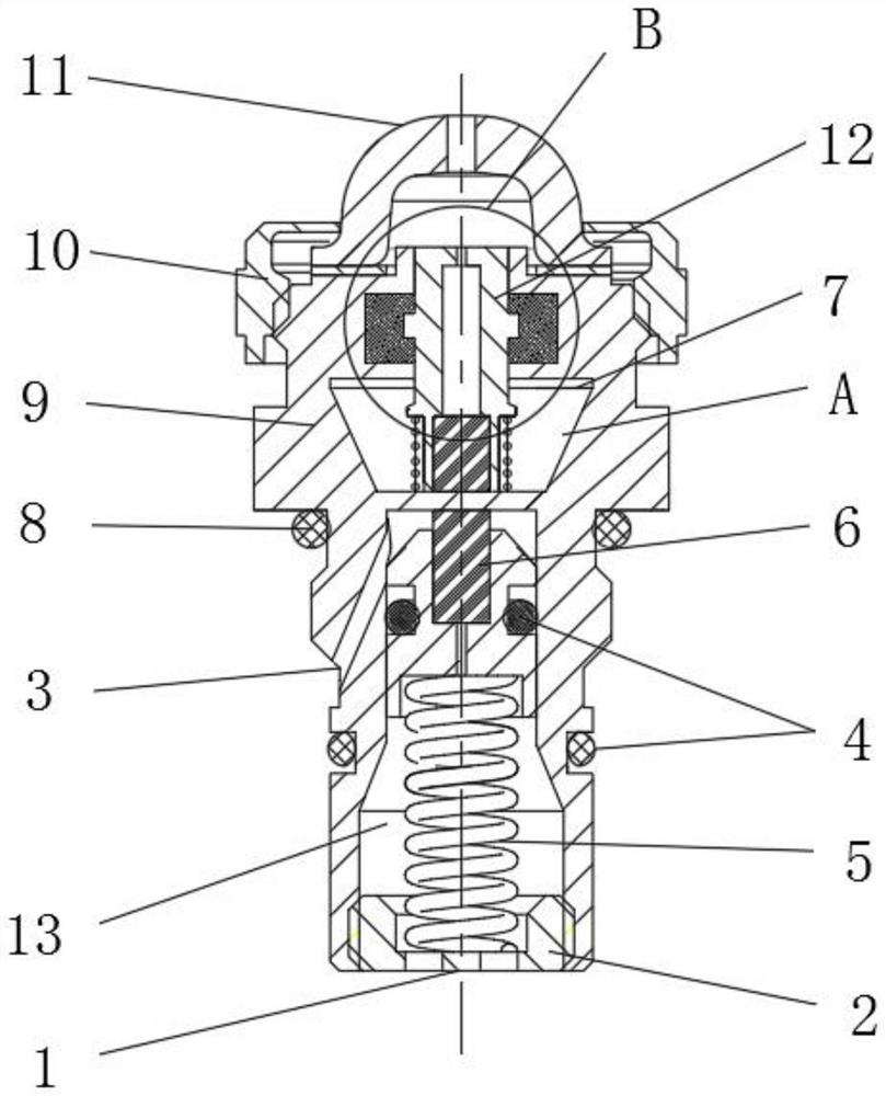
[0029] A differential pressure transmitter that uses liquid metal to control temperature, such as Figure 3-4 As shown, it includes a housing 9, the lower part of the housing 9 and the middle part of the lower end of the housing 9 are respectively provided with a filter oil inlet 3 and a filter oil outlet 1, and the lower end of the housing 9 is fixedly installed with a spring seat 2, a spring seat 2 The lower spring 5 is fixedly installed on the upper part, the lower magnetic steel assembly 6 is fixedly installed on the upper end of the lower spring 5, the upper cavity 7 is opened inside the housing 9, the upper magnetic steel assembly 12 is arranged inside the upper cavity 7, and the upper end of the housing 9 is arranged There is a nut 10, the middle part of the nut 10 is provided with a transparent cover 11, the middle part of the lower magnetic steel assembly 6 and the lower part of the outer surface of the housing 9 are provided with a No. 1 sealing ring 4, and the middle...
PUM
 Abstract
Description
Claims
Application Information
 - R&D Engineer
- R&D Manager
- IP Professional
- Industry Leading Data Capabilities
- Powerful AI technology
- Patent DNA Extraction
Browse by: Latest US Patents, China's latest patents, Technical Efficacy Thesaurus, Application Domain, Technology Topic, Popular Technical Reports.
© 2024 PatSnap. All rights reserved.Legal|Privacy policy|Modern Slavery Act Transparency Statement|Sitemap|About US| Contact US: help@patsnap.com