Inner oil deflector ring of airplane wheel and oil deflector ring assembly of inner oil deflector ring

An oil slinger, wheel technology, applied in the direction of engine components, piston rings, bearing components, etc., can solve the problem of no dynamic seal and static seal, poor sealing effect, and the inner oil slinger does not distinguish between static seal structure and dynamic seal structural issues

Active Publication Date: 2021-05-14
长沙鑫航机轮刹车有限公司
View PDF8 Cites 0 Cited by
  • Summary
  • Abstract
  • Description
  • Claims
  • Application Information

AI Technical Summary

Problems solved by technology

[0004] The Chinese patent application publication number CN 102966672 A discloses an oil slinger assembly for an aircraft wheel. The inner slinger is located at one end of the wheel hub bearing, and the inner slinger is embedded in a groove on the inner wall of the wheel hub. Realize the fixing of the inner oil deflector ring along the axial and circumferential directions of the aircraft wheel, and prevent the lubricating grease in the hub bearing from flowing out through the inner oil deflector ring. However, the inner oil deflector ring in this scheme does not distinguish between the static seal structure and the dynamic seal structure , there is no targeted setting of dynamic seal and static seal, and the sealing effect is not good

Method used


Image

  • Inner oil deflector ring of airplane wheel and oil deflector ring assembly of inner oil deflector ring
  • Inner oil deflector ring of airplane wheel and oil deflector ring assembly of inner oil deflector ring
  • Inner oil deflector ring of airplane wheel and oil deflector ring assembly of inner oil deflector ring

Examples


Embodiment Construction

[0033] The following will clearly and completely describe the technical solutions in the embodiments of the present invention with reference to the accompanying drawings in the embodiments of the present invention. Obviously, the described embodiments are only some, not all, embodiments of the present invention. Based on the embodiments of the present invention, all other embodiments obtained by persons of ordinary skill in the art without making creative efforts belong to the protection scope of the present invention.

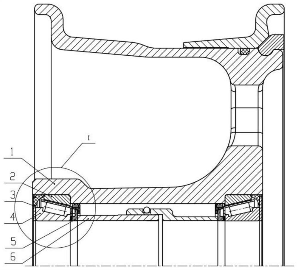
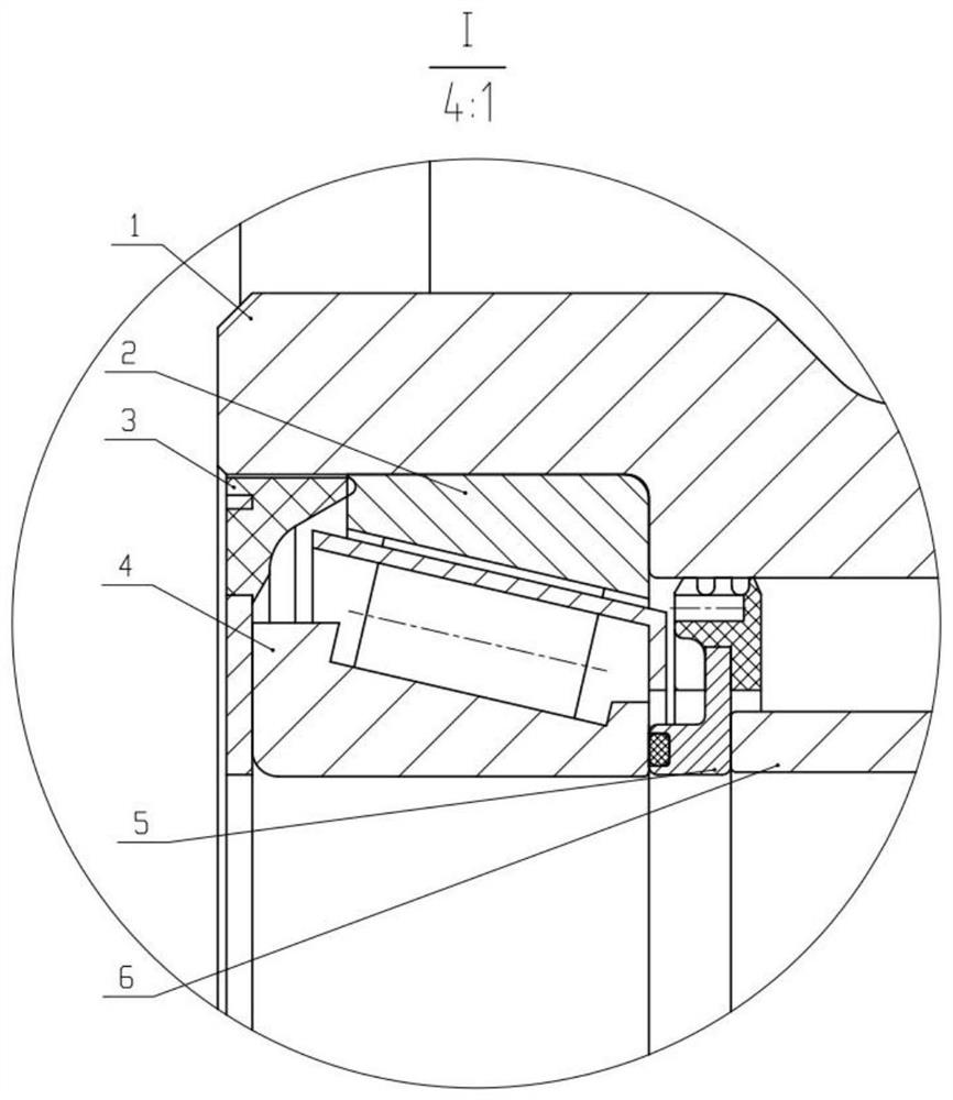
[0034] The purpose of the present invention is to provide a kind of aircraft wheel inner oil deflector ring and its oil deflector ring assembly, to solve the problems existing in the prior art, a dynamic sealing ring and a static sealing ring are detachably arranged on the metal skeleton ring, through The dynamic sealing ring achieves dynamic sealing with the inner diameter side of the wheel, and the static sealing ring realizes static sealing with the inner ri...


PUM


Abstract

The invention discloses an inner oil deflector ring of an airplane wheel and an oil deflector ring assembly of the inner oil deflector ring. The inner oil deflector ring comprises a metal framework ring, a movable sealing ring and a static sealing ring. The movable sealing ring is detachably arranged on the outer diameter side of the metal framework ring. The static sealing ring is detachably arranged on the outer end face of the metal framework ring. The movable sealing ring is in movable sealing with the inner diameter side of the airplane wheel. The static sealing ring is in static sealing with a bearing inner ring of a tapered roller bearing. The oil deflector ring assembly comprises the inner oil deflector ring and further comprises an outer oil deflector ring. The inner oil deflector ring and the outer oil deflector ring are arranged on the inner side and the outer side of the tapered roller bearing correspondingly. According to the inner oil deflector ring of the airplane wheel and the oil deflector ring assembly of the inner oil deflector ring, the movable sealing ring and the static sealing ring are detachably arranged on the metal framework ring, movable sealing with the inner diameter side of the airplane wheel is achieved through the movable sealing ring, static sealing with the bearing inner ring of the tapered roller bearing is achieved through the static sealing ring, the static sealing ring and the movable sealing ring can be made of different structures or materials, and a better sealing effect is achieved.

Description

technical field [0001] The invention relates to the field of aircraft wheels, in particular to an inner oil deflector ring of an aircraft wheel and an oil deflector assembly thereof. Background technique [0002] A tapered roller bearing is arranged between the aircraft wheel and the landing gear shaft, and the relative rotation of the two is realized through the tapered roller bearing. Tapered roller bearings can be divided into outer ring and inner ring. Rollers and cages are arranged between the outer ring and inner ring. Generally, the inner ring, rollers and cage are integrated, which is convenient for installation and disassembly. The outer ring passes through the Ying fit is installed in the wheel bearing hole, and the inner ring is installed on the landing gear shaft, that is to say, when rotating, the outer ring and the wheel rotate, while the inner ring and the landing gear shaft do not rotate. [0003] When tapered roller bearings are used, a large amount of grea...

Claims


Application Information

Patent Timeline
Patent Type & Authority Applications(China)
IPC IPC(8): F16C33/78F16C33/80F16J9/20F16J9/26
CPCF16C33/7813F16C33/80F16C33/783F16C33/782F16J9/20F16J9/26
Inventor 肖卿刘杰张海李婷婷倪新微廖沛霖卢九林
Owner 长沙鑫航机轮刹车有限公司
Why Eureka
Try Eureka