
Roller bearing with microtextures on raceway surfaces of inner and outer rings and machining method thereof

A technology for roller bearings and processing methods, which is applied in the direction of machine tools, bearings, shafts and bearings with surface polishing, can solve the problems that the surface texture structure is not suitable for roller bearings, etc., to improve lubrication performance and load resistance, and improve Physical properties, effects of increased rigidity and strength

Pending Publication Date: 2021-05-14
GUANGZHOU UNIVERSITY
View PDF3 Cites 2 Cited by
  • Summary
  • Abstract
  • Description
  • Claims
  • Application Information

AI Technical Summary

Benefits of technology

This patented technology improves bearings' ability to create hydrodynamic lubrications (HDL) between moving parts while preventing damage caused by excessively high loads or low temperatures. It achieves this through adding a strong material inside the races for better stability at higher speeds than traditional methods. Additionally, it provides a special type of texture called 'microgroove', where tiny holes are formed along one side of each line. These small openings allow lubricant to enter these areas instead of being absorbed onto other surfaces causing them to lose their lubricative power over longer periods. Overall, this innovator design enhances durability and reduces maintenance costs compared with current designs.

Problems solved by technology

This patented technical problem addressed in this patents relates to optimizing the quality (strength) or durability of rolling element bearings used under severe conditions like heavy loads, long hours without stopping working due to poor lubrication efficiency. Surface texture structures made from specific materials may be effective when applied during these applications, while others could lead to improved results compared to regular treatment alone.

Method used


Image

  • Roller bearing with microtextures on raceway surfaces of inner and outer rings and machining method thereof
  • Roller bearing with microtextures on raceway surfaces of inner and outer rings and machining method thereof
  • Roller bearing with microtextures on raceway surfaces of inner and outer rings and machining method thereof

Examples


Embodiment 1

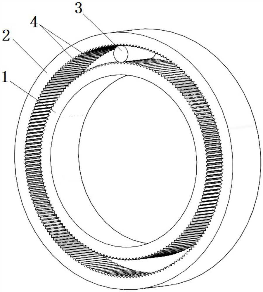
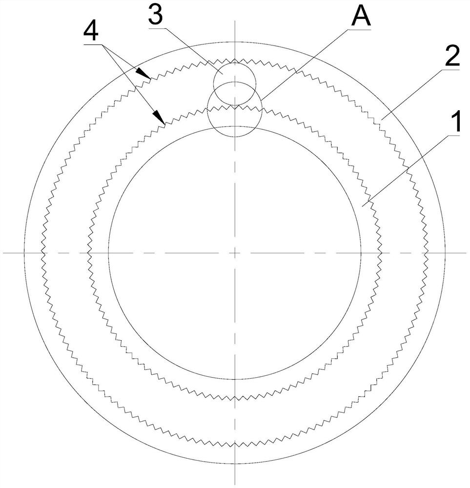
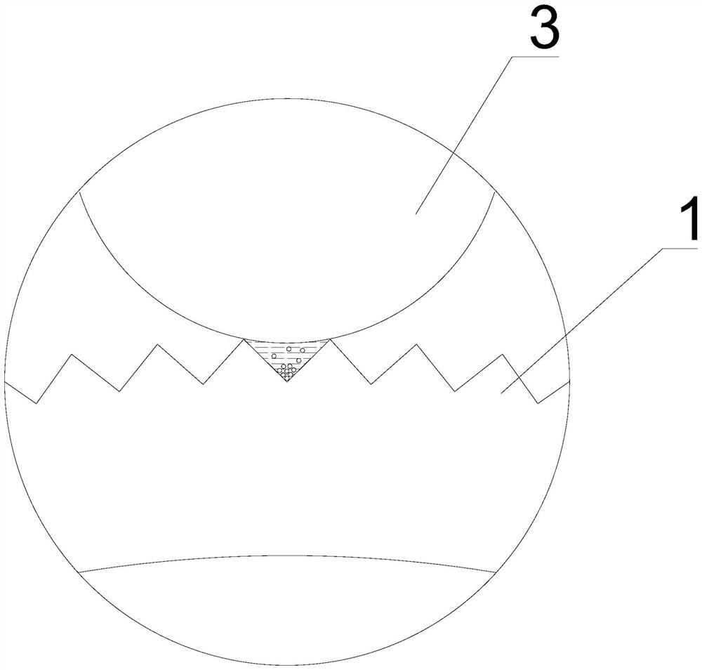
[0058] Among them, for the convenience of viewing, the reference signs are now uniformly explained: 1 is the inner ring of the bearing, 2 is the outer ring of the bearing, 3 is the rolling element, 4 is the vertical groove, 5 is the laser, 6 is the laser beam, and 7 is the convex lens , 8 is the raceway surface of the bearing inner ring, 9 is the workbench, 10 is the raceway surface of the bearing outer ring, 11 is the plane mirror, a is the surface micro-texture layer, b is the chemical and physical film layer containing residual stress spraying, c is the nitrogen-enriched surface strengthening layer containing residual stress, and d is the bearing matrix. where α is the angle of the V-shaped groove, and h is the depth of the V-shaped groove. where F 1 , F 2 is the contact stress on the V-shaped groove, and the magnitude is equal, F 3 for F 1 , F 2 the resultant force.

[0059] In this embodiment, a roller bearing with a micro-texture on the raceway surface of the inner...

Embodiment 2

[0065] This embodiment is a roller bearing with a micro-texture on the raceway surface of the inner and outer rings. An arc, the arc is a circular arc, an elliptical arc, a parabola or other high-order curved arcs.

Embodiment 3

[0067] In this embodiment, a method for processing a roller bearing with a micro-texture on the raceway surface of the inner and outer rings, such as Figure 6-10 shown, including the following steps:

[0068] s1. According to the design size of the roller bearing, the bearing inner ring blank and the bearing outer ring blank are processed, so that the diameter of the bearing inner ring blank is 0.15 mm to 0.25 mm smaller than the design size, and the bearing outer ring blank is smaller than the design size. The diameter is 0.15mm~0.25mm larger;

[0069] s2. Carry out intensified grinding on the raceway surface of the bearing inner ring blank and the raceway surface of the bearing outer ring blank to obtain the bearing inner ring and bearing outer ring that meet the design size, and then the raceway surface of the bearing inner ring and the bearing outer ring The raceway surface of the ring is cleaned;

[0070] s3. Using a multi-axis linkage laser processing system to perfor...


PUM

PropertyMeasurementUnit
Diameteraaaaaaaaaa
Wavelengthaaaaaaaaaa

Abstract

The invention discloses a roller bearing with microtextures on raceway surfaces of inner and outer rings and a machining method thereof. The roller bearing comprises a bearing inner ring, a bearing outer ring and a rolling body, the raceway surface of the bearing inner ring and the raceway surface of the bearing outer ring are correspondingly provided with a strengthened grinding layer, and the surface of each strengthened grinding layer is provided with a microtexture structure; and the microtexture structure comprises a plurality of vertical-strip-shaped grooves which are evenly arranged in the circumferential direction, the depth of each vertical-strip-shaped groove is 3-4 micrometers, and the distance between every two adjacent grooves is 20-40 micrometers. The machining method comprises the steps that a bearing inner ring blank and a bearing outer ring blank are machined, the roller path surface of the bearing inner ring blank and the roller path surface of the bearing outer ring blank are subjected to strengthened grinding machining, and the bearing inner ring and the bearing outer ring meeting the design size are obtained and then cleaned; and a multi-axis linkage laser machining system is used for carrying out rapid laser milling machining, the microtexture structure is prepared, the roller path surface of the bearing inner ring and the roller path surface of the bearing outer ring are cleaned through ultrasonic waves, and then polishing is carried out.

Description


Claims


Application Information

Patent Timeline
Owner GUANGZHOU UNIVERSITY
Learn More