Eureka AIR delivers breakthrough ideas for toughest innovation challenges, trusted by R&D personnel around the world.

Vehicle exhaust particle collection and regeneration device and method thereof, and vehicle

A regeneration device and particle technology, applied in the direction of exhaust device, electric control of exhaust treatment device, exhaust treatment, etc., can solve problems such as flameout and engine damage, and achieve the effect of avoiding engine damage

Active Publication Date: 2022-07-01
GUANGZHOU AUTOMOBILE GROUP CO LTD
View PDF15 Cites 0 Cited by
  • Summary
  • Abstract
  • Description
  • Claims
  • Application Information

AI Technical Summary

Problems solved by technology

However, after the particles are captured, it is necessary to increase the temperature of the GPF through an additional input power supply to burn off the particles. At the same time, if the GPF heating system is damaged, or the GPF itself is damaged, the particles cannot be burned in time, which will lead to excessive pressure and poor airflow, which will cause the engine damage, flameout while the vehicle is in motion, etc.

Method used


Image

  • Vehicle exhaust particle collection and regeneration device and method thereof, and vehicle

Examples


no. 1 example

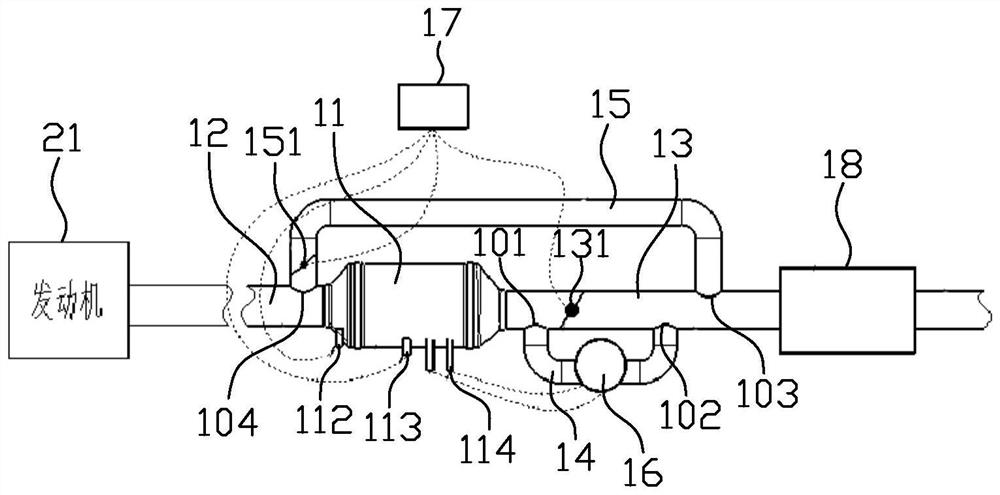
[0034] figure 1 is a schematic diagram of the vehicle exhaust particle collection and regeneration device according to the first embodiment of the present invention, such as figure 1 As shown, the vehicle exhaust particle collection and regeneration device includes a particle collector 11 , an intake pipe 12 , a first exhaust pipe 13 , a second exhaust pipe 14 , a third exhaust pipe 15 , a generator 16 and a control system 17 , the particle collector 11 is provided with a heating network (not shown), one end of the air inlet pipe 12 is connected to the air source, the other end of the air inlet pipe 12 is connected to the air inlet of the particle collector 11, and the first exhaust pipe One end of 13 is connected to the air outlet of the particle collector 11, the first exhaust pipe 13 is provided with a first exhaust valve 131, and the first exhaust pipe 13 is sequentially provided with a first installation hole 101, a first installation hole 101, Two installation holes 102...

no. 2 example

[0051] The present invention also relates to a method for replenishing and regenerating vehicle exhaust particles. The method utilizes the above-mentioned device for replenishing and regenerating vehicle exhaust particles. The method includes:

[0052] S1, when it is detected that the inlet pressure of the particle collector 11 is less than PL, control the first exhaust valve 131 to open, and control the second exhaust valve 151 to close;

[0053] S2, when it is detected that the inlet pressure of the particle collector 11 is greater than Pm, both the first exhaust valve 131 and the second exhaust valve 151 are controlled to be closed, and the airflow passes through the second exhaust pipe 14 to drive the generator 16 to generate electricity and heat The net heats and burns the particles collected by the particle collector 11;

[0054] Wherein, PL is the air inlet pressure of the newly installed particle collector 11; Pm is the air inlet pressure when the particle collector 11...

no. 3 example

[0075] The present invention also relates to a vehicle comprising the above-mentioned vehicle exhaust particle collection and regeneration device.


PUM


Abstract

A device for collecting and regenerating vehicle exhaust particles. The particle collector is provided with a heating net, one end of an air intake pipe is connected to an air source, and the other end of the intake pipe is connected to an air inlet of the particle collector. A first exhaust pipe One end is connected to the air outlet of the particle collector, the first exhaust pipe is provided with a first exhaust valve, the first exhaust pipe is provided with a first installation hole, a second installation hole and a third installation hole, the second row The two ends of the air pipe are respectively connected with the first installation hole and the second installation hole, the generator is connected with the second exhaust pipe, the generator is electrically connected with the heating network, the air intake pipe is provided with a fourth installation hole, and the third installation hole is provided on the intake pipe. The two ends of the exhaust pipe are respectively connected with the third installation hole and the fourth installation hole. The third exhaust pipe is provided with a second exhaust valve, and the control system can control the opening or closing of the first exhaust valve and the second exhaust valve. . The vehicle exhaust particle collection and regeneration device of the present invention can realize regeneration without additional energy. The invention also relates to a vehicle exhaust particle collection regeneration method and a vehicle.

Description

technical field [0001] The present invention relates to the technical field of engine accessories, in particular to a vehicle exhaust particle collection and regeneration device, a method thereof, and a vehicle. Background technique [0002] In order to meet the requirements of the National VI emission regulations, most of the current vehicle emission systems use a particle collector to capture insufficiently burned carbon particles, and the captured particulate matter is burned in a heated particle collector. However, after the particles are captured, the temperature of the GPF needs to be increased by an additional input power supply to burn the particles. At the same time, if the GPF heating system is damaged, or the GPF itself is damaged, the particles cannot be burned in time, which will lead to excessive pressure and poor airflow. Danger of damage, stalling of the vehicle while driving, etc. SUMMARY OF THE INVENTION [0003] In view of this, the present invention pr...

Claims


Application Information

Patent Timeline
Patent Type & Authority Patents(China)
IPC IPC(8): F01N3/027F01N9/00F01N5/02
CPCF01N3/027F01N9/002F01N5/025F01N2240/04F01N2240/16F01N2590/08F01N2900/1602Y02T10/12
Inventor 黄兴来张宁李薛曾志新钟灵贵钟广桦
Owner GUANGZHOU AUTOMOBILE GROUP CO LTD
Why Eureka
Eureka Blog
Learn More