
Automatic spraying device

An automatic spraying and sliding installation technology, applied in printing devices, printing, etc., can solve the problems of low product switching efficiency, poor spraying quality in border areas, and low spraying efficiency, so as to improve the functionality and effect of use, and increase the scope of application , good effect

Pending Publication Date: 2021-05-14
SHENZHEN TENSUN IND EQUIP
View PDF11 Cites 0 Cited by
  • Summary
  • Abstract
  • Description
  • Claims
  • Application Information

AI Technical Summary

Problems solved by technology

[0003] Nowadays, many spraying devices adopt single-nozzle spot spraying method: only the spraying from point to line and from line to surface can be realized. In the transition area, the spraying boundary in the line direction is fuzzy, and the spraying quality in the boundary area is poor. Screen printing: the cost of screen plate making is high, the process is cumbersome, it can only be printed in one color, the color difference control ability is poor, the product switching efficiency is low, and the ink utilization is low. Ultrasonic or pneumatic spraying: Irregular boundaries, difficult to control dimensional accuracy, unable to achieve complex pattern spraying and precise positioning spraying, and at the same time, some blasting devices are installed in today's spraying devices as a rapid air-drying structure for the surface after spraying. However, the structure after spraying is not air-dried while moving, and the air-drying fan needs an independent driving mechanism to drive, and the position of the air-drying fan is fixed. The air-drying effect of the sprayed surface in the overall device is not good, and certain improvements are needed

Method used


Image

  • Automatic spraying device
  • Automatic spraying device
  • Automatic spraying device

Examples


Embodiment Construction

[0035] The technical solutions of the present invention will be further described below in conjunction with the accompanying drawings and through specific implementation methods.

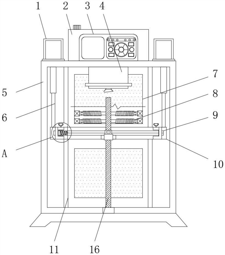
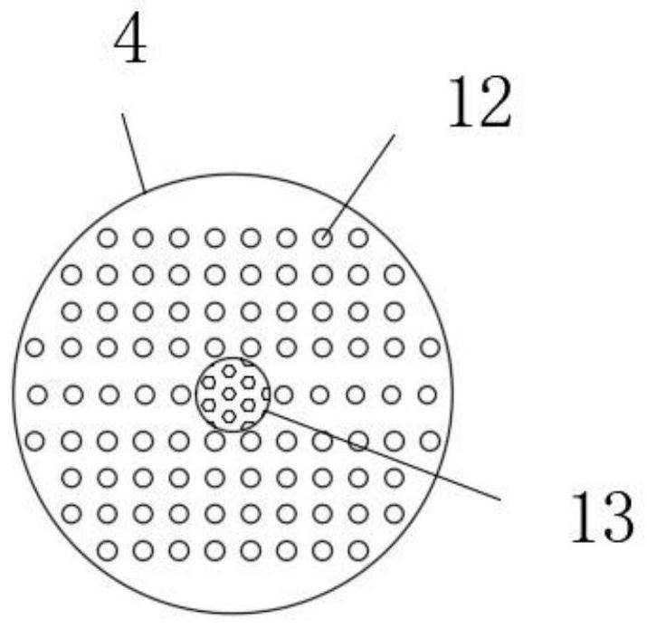
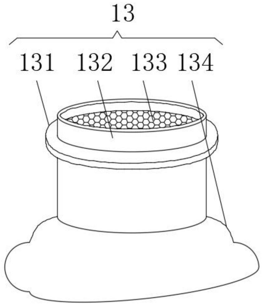
[0036] Such as Figure 1-8As shown, an automatic spraying device is provided in the embodiment, including a casing 5, a rotary spray head mechanism 13, a fixed assembly 14, a threaded rotary sleeve 17, an installation bottom sleeve 19 and a second built-in connection spring 22, the casing 5 An electric push rod 1, an ink tank 2 and a host computer 3 are fixedly installed on the top of the cabinet, and a paint sprayer 4 is fixedly installed on the inner top wall of the casing 5, and a mounting hole is provided at the center of the paint sprayer 4 for installation. A rotating spray head mechanism 13 is installed in the hole, and a number of spraying holes 12 are arranged on the bottom surface of the paint sprayer 4. A telescopic rod 6 is installed on the output end of the electric push rod 1, and one ...


PUM


Abstract

The invention discloses an automatic spraying device, and belongs to the technical field of spraying. The automatic spraying device comprises a machine shell, a rotary spray head mechanism, a fixing assembly, a threaded rotating sleeve, a mounting bottom sleeve and a second built-in connecting spring, wherein an electric push rod, a printing ink box and an upper computer are fixedly mounted at the top of the machine shell, a paint sprayer is fixedly mounted on the inner top wall of the machine shell, and a mounting hole is formed in the center position of the paint sprayer. According to the automatic spraying device, a plurality of spraying holes are formed in the bottom of the paint sprayer, during spraying operation, a single sprayer can achieve simultaneous spraying of multiple nozzles, large-area low-flow high-speed droplet coating operation is rapidly achieved, and compared with the prior art, the efficiency is obviously improved; meanwhile, the upper computer is arranged on the automatic spraying device, stepping type spraying of fixed patterns can be achieved according to dot matrix information obtained by the system, spraying of complex patterns is achieved under the condition that multi-axis linkage control is not needed, the applicability is wide, and the using functionality and the using effect of the spraying device are improved.

Description

technical field [0001] 本发明涉及喷涂技术领域,更具体的,涉及一种自动喷涂装置。 Background technique [0002] 喷涂一般通过喷枪或碟式雾化器,借助于压力或离心力,分散成均匀而微细的雾滴,施涂于被涂物表面的涂装方法。可分为空气喷涂、无空气喷涂、静电喷涂以及上述基本喷涂形式的各种派生的方式,如大流量低压力雾化喷涂、热喷涂、自动喷涂、多组喷涂等,喷涂装置的种类很多,不同的喷涂装置的喷涂效果也不同。 [0003] 现如今许多喷涂装置采用单喷嘴点喷方式:只能实现由点成线,由线成面的喷涂,喷涂效率低下,单工序工艺时间长,且单喷嘴线喷方式:线喷边缘存在超喷过渡区,线型方向喷涂边界模糊,边界区域喷涂质量差,网版印刷:网版制版费用高,工序繁琐,只能单色印刷,色差控制能力差,产品切换效率低,油墨利用率低,超声或气动喷涂:边界不规则,尺寸精度难以控制,不能实现复杂图案的喷涂成形,不能实现精确定位喷涂,同时现如今的喷涂装置内设置有一些鼓风装置作为喷涂后的表面快速风干结构,但喷涂后的结构并未在移动中进行风干,且风干风扇需要独立的驱动机构去驱动,且风干风扇位置固定,整体装置内喷涂面风干效果不佳,需要进行一定改进。 Contents of the invention [0004] 为了克服现有技术的缺陷,本发明所要解决的技术问题在于提出一种自动喷涂装置,其能够满足扩展喷漆范围且具有快速有效喷涂面烘干效果的特点。 [0005] For reaching this purpose, the present invention adopts following technical scheme: [0006] 本发明提供了一种自动喷涂装置,包括机壳、旋转喷头机构、固定组件、螺纹转套、安装底套和第二内置连接弹簧,所述机壳的顶部固定安装有电动推杆、油墨箱与上位机,所述机壳的内顶壁上固定安装有喷漆器,所述喷漆器的中心位置处开设有安装孔,安装孔内转动安装有旋转喷头机构,喷漆器的底面上设置有若干喷涂孔,所述电动推杆的输出端上安装有伸缩杆,伸缩杆一端穿过并延伸至机壳的内部固定安装有内安装板,所述内安装板的侧面开设有行程槽,所述行程槽的内部滑动安装有两个固定组件,两个固定组件之间通过第二内置连接弹簧连接,所述机壳的内部...

Claims


Application Information

Patent Timeline
Patent Type & Authority Applications(China)
IPC IPC(8): B41J2/01B41J11/00
CPCB41J2/01B41J11/00B41J11/0015B41J11/002
Inventor 卢国明卢国艺张涛江岱平曾金城易智勇
Owner SHENZHEN TENSUN IND EQUIP
Learn More