Injection squeezing machine
A technology of injection press and material injection, which is applied to presses, manufacturing tools, etc., can solve the problems of low efficiency and high cost
- Summary
- Abstract
- Description
- Claims
- Application Information
AI Technical Summary
Problems solved by technology
Method used
Image

Examples
Embodiment 1
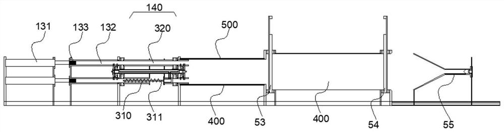
[0072] like figure 1 - Figure 12As shown, the injection press machine provided by the embodiment of the present invention includes: a material injection device and a separation bin 400, and the separation bin 400 includes a separation bin inlet and a separation bin outlet at both ends thereof, and the injection device and the separation bin 400 The feed port of the separation bin is connected, and the injection device is used for injecting materials into the separation bin 400 . There is continuous material input at the inlet of the separation chamber, the outlet of the separation chamber is smaller than the inlet of the separation chamber, and the outlet of the separation chamber is gradually filled with solid materials, and the discharge speed is lower than the feed speed, or the discharge of the separation chamber can be temporarily closed mouth. Materials enter and gather in the separation bin 400, and gradually move along the inlet of the separation bin to the side of ...
Embodiment approach
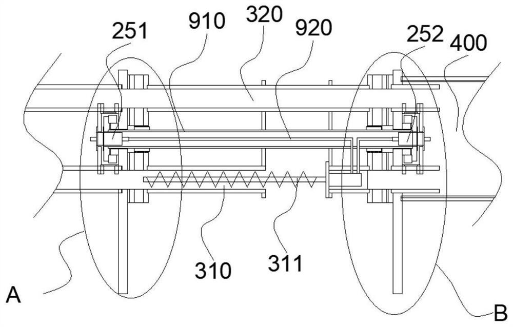
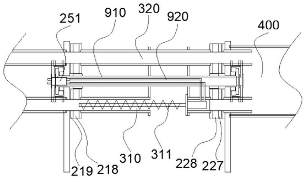
[0106] like figure 1 - Figure 7 As shown, the reversing drive mechanism may include a reversing driving power machine and a reversing rotating shaft 910, and the reversing driving power machine drives the reversing rotating shaft 910 to rotate; the reversing rotating shaft 910 forms the inner rotating member, and the outer rotating member It may be a sleeve structure sleeved on the outside of the reversing shaft 910 . The reversing shaft 910 is provided with a hydraulic rotary joint, an electric rotary joint or a pneumatic rotary joint, and the hydraulic rotary joint, electric rotary joint or pneumatic rotary joint is connected to the lead material through a hydraulic pipeline, a cable or a pneumatic pipeline 920. The mechanism 311 is connected to and transmits energy to the material introduction mechanism 311, and the hydraulic rotary joint, electric rotary joint or pneumatic rotary joint is arranged in the reversing shaft 910, so that the volume of the device can be reduce...
Embodiment 2
[0159] Such as Figure 16As shown, the injection device includes an injection cavity 111 and a material delivery mechanism, and the delivery mechanism may be a rotary delivery mechanism 112; the injection cavity 111 includes an inlet of the injection cavity 111 and a discharge of the injection cavity 111 The outlet of the injection chamber 111 is connected to the inlet of the separation bin, the delivery mechanism is arranged in the injection cavity 111, the rotary delivery mechanism 112 can include a spiral structure, the injection cavity 111 The material inlet and the material outlet of the material injection cavity 111 are respectively located at the opposite ends of the spiral structure, and the material delivery mechanism is used to continuously input the material in the material injection cavity 111 into the separation bin 400, so as to The high pressure is generated in the separation chamber 400. During the continuous input of materials into the separation chamber 400, ...
PUM
 Abstract
Description
Claims
Application Information
 - Generate Ideas
- Intellectual Property
- Life Sciences
- Materials
- Tech Scout
- Unparalleled Data Quality
- Higher Quality Content
- 60% Fewer Hallucinations
Browse by: Latest US Patents, China's latest patents, Technical Efficacy Thesaurus, Application Domain, Technology Topic, Popular Technical Reports.
© 2025 PatSnap. All rights reserved.Legal|Privacy policy|Modern Slavery Act Transparency Statement|Sitemap|About US| Contact US: help@patsnap.com