Broom wooden handle bottom cutting equipment

A technology of cutting equipment and wooden handle, applied in the field of cutting equipment at the bottom of wooden handle of brooms, can solve the problems of scattered wood chips, high work intensity, inconvenient cleaning and the like

Active Publication Date: 2021-05-14
江苏金鼎建设集团有限公司
View PDF10 Cites 4 Cited by
  • Summary
  • Abstract
  • Description
  • Claims
  • Application Information

AI Technical Summary

Problems solved by technology

[0005] In order to overcome the above disadvantages of high work intensity when manually cutting the bottom of the wooden handle, the need to manually hold the wooden handle during cutting, and the inconvenient cleaning of sawdust scattered around after cutting, the technical problem to be solved is: provide a broom handle bottom Automatic cutting and automatic clamping of broom handle bottom cutting equipment that prevents wood chips from flying around when cutting the wooden handle

Method used


Image

  • Broom wooden handle bottom cutting equipment
  • Broom wooden handle bottom cutting equipment
  • Broom wooden handle bottom cutting equipment

Examples


Embodiment 1

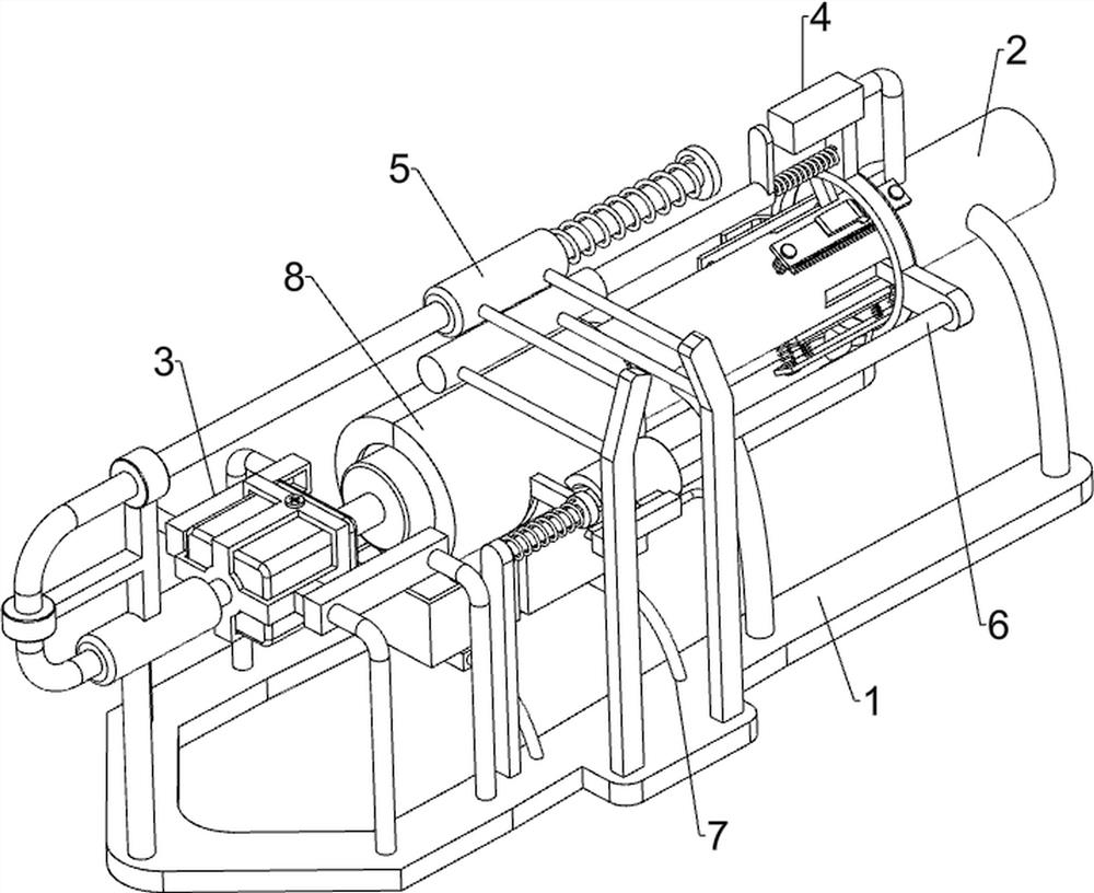
[0029] A broom handle bottom cutting device such as figure 1 As shown, it includes a base 1 , a placement mechanism 2 and a cutting mechanism 3 , the top right side of the base 1 is provided with the placement mechanism 2 , and the top left side of the base 1 is provided with the cutting mechanism 3 .

[0030] When it is necessary to cut the bottom of the wooden handle, first place the wooden handle in the placing mechanism 2, manually clamp the wooden handle through the parts of the placing mechanism 2, then open the cutting mechanism 3, and manually push the parts of the cutting mechanism 3 to the right Move and cut the bottom of the wooden handle. After cutting, loosen the parts of the placement mechanism 2, no longer clamp the wooden handle, take out the wooden handle, and close the cutting mechanism 3.

Embodiment 2

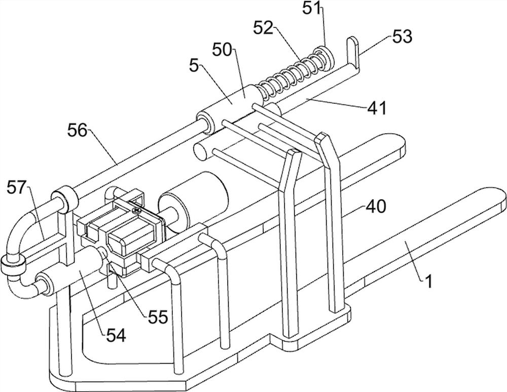
[0032] On the basis of Example 1, such as figure 1 , figure 2 , image 3 with Figure 4 As shown, the placement mechanism 2 includes a placement cylinder 20, a clamping block 21, a slide bar 22, a slide plate 23, a first spring 24, and a second spring 25, and the placement cylinder 20 is arranged between the front and rear of the top right side of the base 1, and the placement cylinder The middle part of 20 is provided with a clamping block 21 which is evenly slidable in the circumferential direction, and the placement tube 20 is symmetrically provided with slide bars 22. The number of slide bars 22 is 8, and the slide bars 22 are respectively located on both sides of the clamp block 21 at the same horizontal level. A slide plate 23 is provided in a sliding manner between the slide bars 22, and a first spring 24 is connected between the left and right sides of the slide plate 23 and the placement tube 20, and the first spring 24 is sleeved on the first slide bar 22, and the...

Embodiment 3

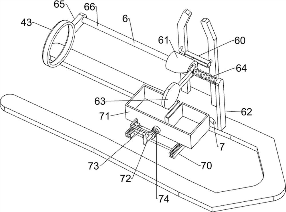
[0037] On the basis of Example 2, such as figure 1 , Figure 5 , Image 6 , Figure 7 with Figure 8 As shown, an automatic clamping assembly 4 is also included, and the automatic clamping assembly 4 includes a mounting plate 40, an electric push rod 41, a wedge block 42, a sliding ring 43, a sliding rail 44, a sliding block 45 and a third spring 46, the base 1. A mounting plate 40 is symmetrically arranged in the middle part of the front side of the top, an electric push rod 41 is provided between the upper part of the rear side of the mounting plate 40, a wedge-shaped block 42 is provided in the middle part of the outer side of the slide plate 23, and a sliding ring 43 is provided in the middle part of the storage tube 20 for sliding, Sliding ring 43 cooperates with wedge-shaped block 42, is provided with sliding rail 44 on the upper part of placing tube 20 right sides, and sliding type is provided with slider 45 on sliding rail 44, and the bottom of sliding block 45 is c...


PUM


Abstract

The invention relates to cutting equipment, in particular to broom wooden handle bottom cutting equipment, and aims to solve the technical problem about how to provide the broom wooden handle bottom cutting equipment which can cut and clamp the bottom of a wooden handle of a broom automatically and can prevent wood chips from flying around when the wooden handle is cut. The broom wooden handle bottom cutting equipment comprises a base, a placing mechanism and a cutting mechanism; the placing mechanism is arranged on one side of the top of the base; the cutting mechanism is arranged on the side, away from the placing mechanism, of the top of the base. The effects that the bottom of the wooden handle of the broom is automatically cut and automatically clamped, and the wood chips cannot fly around when the wooden handle is cut are achieved; a cutting tool is driven by a servo motor to rotate to cut the wooden handle, so that the purpose of automatic cutting is achieved; before the servo motor and the cutting tool move towards the right side to cut the wooden handle, a sliding ring moves towards the left side to press a sliding plate to extrude towards the inner side through a wedge-shaped block, and thus the wooden handle is clamped.

Description

technical field [0001] The invention relates to a cutting device, in particular to a cutting device for the bottom of a broom handle. Background technique [0002] Broom is the most common living tool in family and work, and it also plays a pivotal role in human's healthy life and family cleaning. [0003] The broom consists of a wooden handle and a broom. During the production process of the wooden handle, the bottom of the wooden handle needs to be sharpened to facilitate the installation between the wooden handle and the broom. Usually, the method of cutting the bottom of the wooden handle is manual cutting, manual cutting The work intensity is high, and manual cutting requires manual support of the wooden handle to prevent the wooden handle from tipping over easily during cutting. After cutting, the generated sawdust falls on the ground, which is inconvenient to clean up. [0004] Based on the above-mentioned problems in manually cutting the bottom of the wooden handle,...

Claims


Application Information

Patent Timeline
Patent Type & Authority Applications(China)
IPC IPC(8): B27C5/00B27G3/00
CPCB27C5/00B27G3/00
Inventor 罗成
Owner 江苏金鼎建设集团有限公司
Why Eureka
Try Eureka