Wiring frame structure, wiring terminal and low-voltage electric appliance
A terminal block and terminal frame technology, applied in the direction of circuits, electric switches, electrical components, etc., can solve the problems of product temperature rise, poor reliability, and contact resistance increase
- Summary
- Abstract
- Description
- Claims
- Application Information
AI Technical Summary
Problems solved by technology
Method used
Image
Examples
Embodiment 1
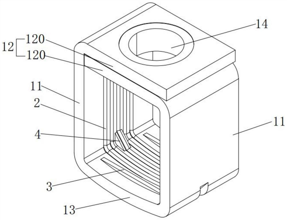
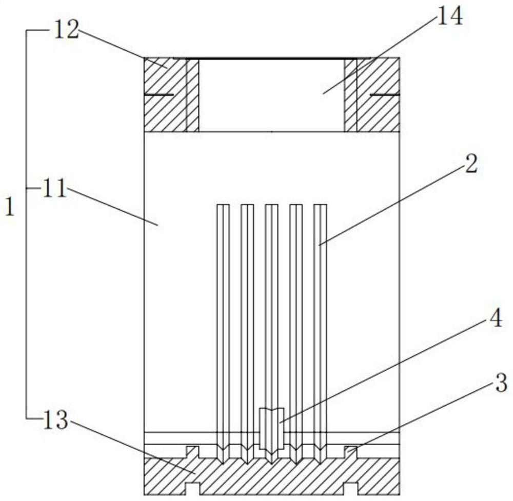
[0045] The wiring frame structure of this embodiment, see Figure 1 to Figure 4 As shown, the wiring frame 1 is included, and the wiring frame 1 is a frame structure surrounded by a top edge 12, two side edges 11 and a bottom edge 13, and has a wiring cavity for wires to pass through and be fixed therein. Specifically, it also includes at least one avoidance structure 2 disposed on the inner wall of at least one side 11 facing away from the wiring cavity, and the avoidance structure 2 is suitable for providing avoidance space for the expansion of the wire when the wire fixed in the wiring cavity is energized and heated. . Through the setting of the avoidance structure 2, when the wire is heated and expanded, the wire can be squeezed into the avoidance structure, and at the same time, the contact area between the wire and the wiring frame is increased, the contact resistance is reduced, and the wire, especially the aluminum wire, can be reduced. After the alternating work of h...
Embodiment 2
[0051] For the connection terminal of this embodiment, see Figure 1 to Figure 4 As shown, it includes a wiring frame 1, a wiring board 5 and a wiring screw 6. The junction frame 1 is the junction frame structure of the first embodiment, and the top edge 12 is provided with an avoidance hole 14 . Wiring board 5 is movably arranged in the wiring cavity. The terminal screw 6 is threadedly connected in the avoidance hole 14 and pressed against the terminal board 5. When the terminal screw 6 rotates, it drives the terminal frame 1 to move relative to the terminal board 5 in the axial direction perpendicular to the terminal cavity, so as to compress or loosen Wires that pass through the wiring cavity. Specifically, such as figure 1 As shown, when the terminal screw 6 rotates, it drives the terminal frame 1 to press on the wire when it moves vertically upwards, and loosens the wire when it moves vertically downward.
[0052] Preferably, one end of the wiring board 5 facing away ...
Embodiment 3
[0058] The low-voltage electrical appliance of this embodiment, such as Figure 1 to Figure 4 As shown, the connection terminal of embodiment 2 is included.
[0059] Since the connecting terminal of Embodiment 2 is used, at least the advantages of the junction frame structure of Embodiment 1 are also provided, and details will not be repeated here.
[0060] Optionally, the low-voltage electrical appliances in this embodiment may be switches, circuit breakers, fuses, contactors, relays and so on. Preferably, the low-voltage electrical appliance in this embodiment is a circuit breaker.
PUM
| Property | Measurement | Unit |
|---|---|---|
| Angle | aaaaa | aaaaa |
| Groove depth | aaaaa | aaaaa |
Abstract
Description
Claims
Application Information
 - R&D
- Intellectual Property
- Life Sciences
- Materials
- Tech Scout
- Unparalleled Data Quality
- Higher Quality Content
- 60% Fewer Hallucinations
Browse by: Latest US Patents, China's latest patents, Technical Efficacy Thesaurus, Application Domain, Technology Topic, Popular Technical Reports.
© 2025 PatSnap. All rights reserved.Legal|Privacy policy|Modern Slavery Act Transparency Statement|Sitemap|About US| Contact US: help@patsnap.com


