
Particle generating device

A generation device, particle technology, applied in the direction of measuring device, individual particle analysis, particle and sedimentation analysis, etc., can solve the problems of reducing the nitrogen flow rate of the quenching flame, fuel combustion, fuel waste, etc.

Active Publication Date: 2021-05-11
WEICHAI POWER CO LTD
View PDF14 Cites 0 Cited by
  • Summary
  • Abstract
  • Description
  • Claims
  • Application Information

AI Technical Summary

Problems solved by technology

[0003] The flow rate of the diluent entering the combustion chamber in the particle generating device in the prior art is fixed, and the size of the flame is further controlled by controlling the flow rate of fuel propane. The flame needs to be increased when the particles are used, but the nitrogen flow rate for quenching the flame cannot be adjusted according to the corresponding ratio, which will cause part of the fuel to burn and cause fuel waste

Method used


Image

  • Particle generating device

Examples


Embodiment Construction

[0025] Embodiments of the present invention are described in detail below, examples of which are illustrated in the accompanying drawings, wherein the same or similar reference numerals refer to the same or similar elements or elements having the same or similar functions throughout. The embodiments described below with reference to the accompanying drawings are exemplary, and are intended to explain the present invention and should not be construed as limiting the present invention.

[0026] In the description of the present invention, it should be noted that the terms "center", "upper", "lower", "left", "right", "vertical", "horizontal", "inner", "outer", etc. The indicated orientation or positional relationship is based on the orientation or positional relationship shown in the accompanying drawings, which is only for the convenience of describing the present invention and simplifying the description, rather than indicating or implying that the indicated device or element mu...


PUM


Abstract

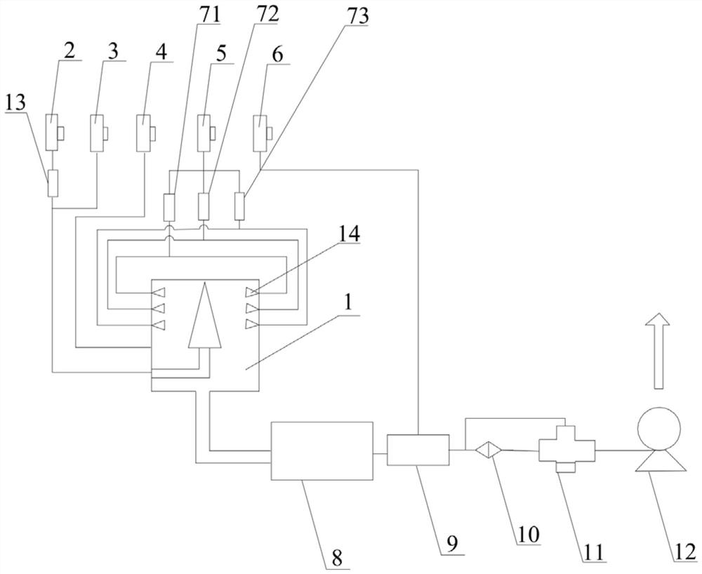
The invention discloses a particle generating device, and relates to the technical field of detection of particle counters and smoke meters. The particle generating device comprises a combustion chamber, a plurality of nozzles and a pump body, fuel and a first diluent in a fixed proportion are introduced into the combustion chamber and then are ignited, and a combustion improver is used for supporting combustion so as to form diffusion flames with a fixed height. The plurality of nozzles are arranged on the side wall of the combustion chamber at intervals in the height direction of diffusion flames, the nozzles are all connected with an inert gas source, and switch valves are arranged between the nozzles located at different heights and the inert gas source; and particles generated in the combustion chamber are discharged through a pump body. The particle generating device provided by the invention can generate particles with higher efficiency, the particle size of the particles is convenient to control, the particle size of the particles is accurately controlled, the working efficiency is improved, and the fuel loss is reduced.

Description

technical field [0001] The invention relates to the detection technology field of particle counters and smoke meters, in particular to a particle generating device. Background technique [0002] With increasingly stringent emission standards, particle counters have played a very important role in testing. At present, in the detection of the particle counter, it is necessary to simulate the soot particles generated by the combustion chamber of the engine, and it is necessary to simulate the passage of particles of different numbers and particle sizes into the particle counter to judge whether the measurement of the particle counter is accurate and whether the linear index meets the standard. [0003] The flow rate of the diluent entering the combustion chamber of the particle generating device in the prior art is fixed, and the size of the flame is further controlled by controlling the flow rate of fuel propane. When small-sized particles are generated, the flame needs to be ...

Claims


Application Information

Patent Timeline
Patent Type & Authority Applications(China)
IPC IPC(8): G01N15/10
CPCG01N15/10
Inventor 雒仲阳别玉敏刘帅王绪龙
Owner WEICHAI POWER CO LTD
Learn More