
Anti-swing floating type anti-collision device

An anti-collision device and anti-sway technology, used in bridge parts, climate change adaptation, bridges, etc., can solve the problems of fatigue damage of anti-collision devices, affecting service life, impacting piers, etc., to achieve good buffering and anti-collision performance, anti-sway The effect of performance, effective performance

Inactive Publication Date: 2021-05-11
李婷
View PDF0 Cites 0 Cited by
  • Summary
  • Abstract
  • Description
  • Claims
  • Application Information

AI Technical Summary

Problems solved by technology

[0003] The purpose of the present invention is to solve the most extensive anti-collision device in the prior art, which can maintain its own stability in an environment with small fluctuations in the water surface, but in the case of strong winds and waves, the anti-collision system will The crests and troughs swing back and forth, function or up and down. If the swing is frequent or too large, it will not only cause fatigue damage to the entire anti-collision device, but also cause damage to the bridge pier due to the swing and hit the pier, which affects the service life. Anti-sway floating anti-collision device

Method used


Image

  • Anti-swing floating type anti-collision device
  • Anti-swing floating type anti-collision device

Examples


Embodiment Construction

[0018] The following will clearly and completely describe the technical solutions in the embodiments of the present invention with reference to the accompanying drawings in the embodiments of the present invention. Obviously, the described embodiments are only some, not all, embodiments of the present invention.

[0019] In describing the present invention, it should be understood that the terms "upper", "lower", "front", "rear", "left", "right", "top", "bottom", "inner", " The orientation or positional relationship indicated by "outside", etc. is based on the orientation or positional relationship shown in the drawings, and is only for the convenience of describing the present invention and simplifying the description, rather than indicating or implying that the referred device or element must have a specific orientation, so as to Specific orientation configurations and operations, therefore, are not to be construed as limitations on the invention.

[0020] refer to Figure ...


PUM


Abstract

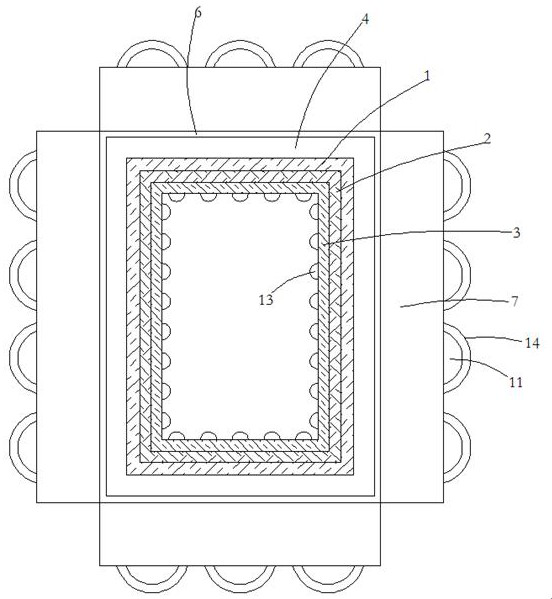
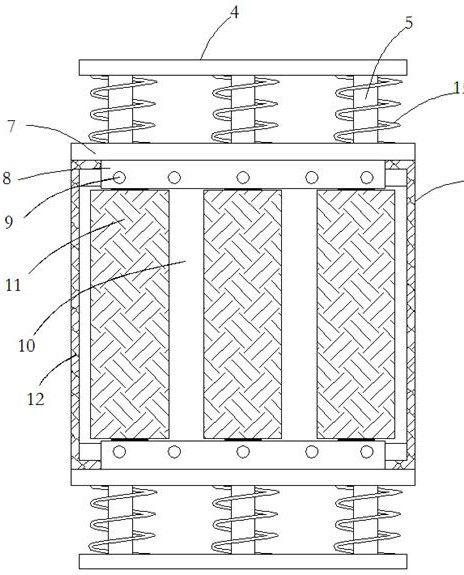
The invention relates to the technical field of anti-collision equipment, and discloses an anti-swing floating type anti-collision device. The anti-swing floating type anti-collision device comprises a steel floating body arranged outside a pier in a sleeving mode, the inner wall of the steel floating body is fixedly connected with a layer of buffering rubber block, the inner side of the buffering rubber block is fixedly connected with a fixing frame, and the outer wall of the steel floating body is fixedly sleeved with two fixing ring plates in an up-down symmetrical mode; a plurality of guide columns are evenly and fixedly connected between the side walls of the opposite sides of the two fixing ring plates, the plurality of guide columns are movably sleeved with a rectangular supporting block arranged outside the steel floating body in a sleeving mode, and guide holes movably arranged outside the guide columns in a sleeving mode are formed in the upper end of the rectangular supporting block; a plurality of buffer springs arranged outside the guide columns in a sleeving mode are fixedly connected between the side walls of the opposite sides of each fixed annular plate and the rectangular supporting block; and two transverse plates are fixedly connected to the outer walls of the four sides of the rectangular supporting block in a vertically symmetrical mode. The anti-collision device has effective anti-swing performance, and the anti-collision performance of the anti-collision device is effectively improved.

Description

technical field [0001] The invention relates to the technical field of anti-collision equipment, in particular to an anti-sway floating anti-collision device. Background technique [0002] As the country pays more and more attention to bridges and other underwater structures that are vulnerable to impact, new or existing bridges and other underwater structures are required to be equipped with anti-collision devices. In the environment, it can maintain its own stability, but in the case of strong winds and waves, the anti-collision system will swing back and forth, function or up and down with the peaks and valleys. If the swing range is frequent or too large, it will not only cause the entire anti-collision device to fail. Fatigue damage will also cause damage to the pier due to swinging and impacting the pier, which affects the service life. Contents of the invention [0003] The purpose of the present invention is to solve the most extensive anti-collision device in the...

Claims


Application Information

Patent Timeline
Patent Type & Authority Applications(China)
IPC IPC(8): E02B3/26E01D19/02
CPCE01D19/02E02B3/26Y02A30/30
Inventor 不公告发明人
Owner 李婷
Learn More