
Constant-tension dancing roller control device

A control device, constant tension technology, used in transportation and packaging, final product manufacturing, sustainable manufacturing/processing, etc., can solve problems such as sticking, prolong production time, pull breakage or unevenness, and achieve extended buffer distance. Effect

Active Publication Date: 2021-05-11
CHANGZHOU RUISAI ELECTROMECHANICAL EQUIP CO LTD +1
View PDF7 Cites 3 Cited by
  • Summary
  • Abstract
  • Description
  • Claims
  • Application Information

AI Technical Summary

Problems solved by technology

[0002] Due to the speed difference between the tension roller speed and the unwinding speed of the tension adjustment device in the prior art, in order to avoid the product from being pulled, broken or uneven, it is necessary to adjust the tension. In the prior art, a balance swing arm is often set to adjust the product. The tension during unwinding, but in the actual production process, when the speed difference exceeds the preset value, the balance swing arm will swing, because the film material provided by the swing alone has little room for adjustment, it is not suitable for high-speed production lines, and it is easy to reach the upper limit and get stuck Dead, the entire unwinding system needs to be adjusted accordingly after being stuck, the workload of the on-site operation is heavy, and the production time is prolonged and the production efficiency is reduced
The swing angle of the balance swing arm is large, causing a large change in tension

Method used


Image

  • Constant-tension dancing roller control device
  • Constant-tension dancing roller control device
  • Constant-tension dancing roller control device

Examples


Embodiment Construction

[0031] The following will clearly and completely describe the technical solutions in the embodiments of the present invention with reference to the accompanying drawings in the embodiments of the present invention. Obviously, the described embodiments are only some, not all, embodiments of the present invention.

[0032] It should be noted that when an element is referred to as being "fixed" to another element, it can be directly on the other element or there may be an intervening element. When an element is said to be "connected" to another element, it can be directly connected to the other element or intervening elements may also be present. The terms "vertical," "horizontal," "left," "right," and similar expressions are used herein for purposes of illustration only and are not intended to represent exclusive embodiments.

[0033] Unless otherwise defined, all technical and scientific terms used herein have the same meaning as commonly understood by one of ordinary skill in ...


PUM


Abstract

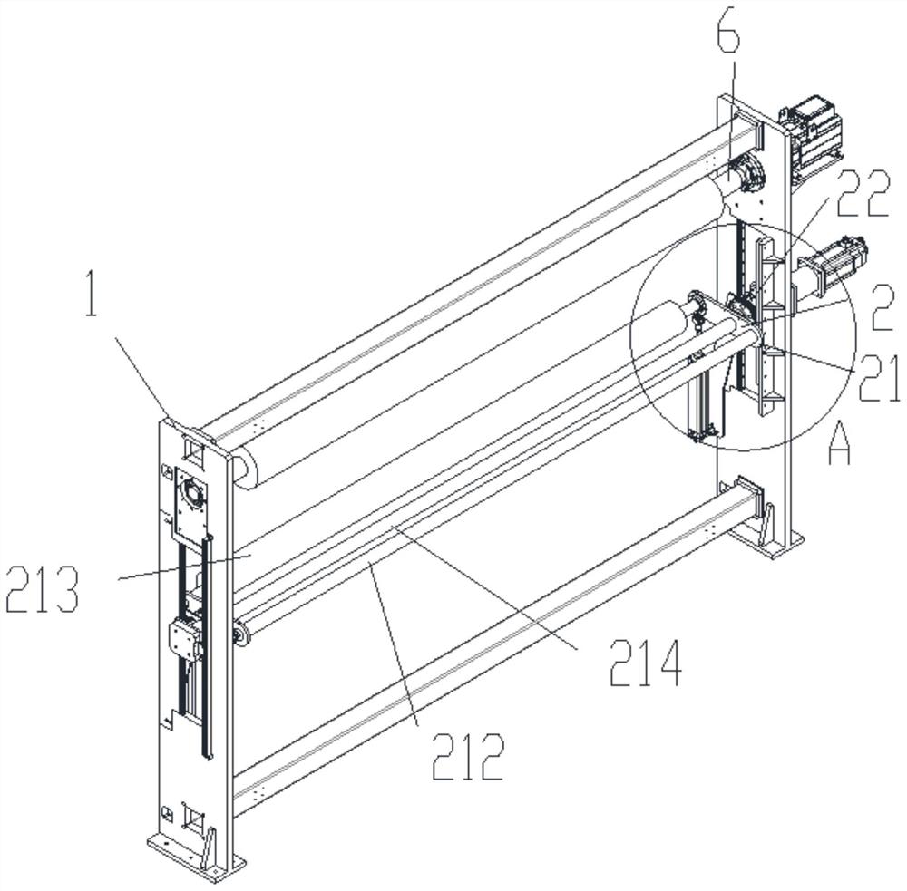
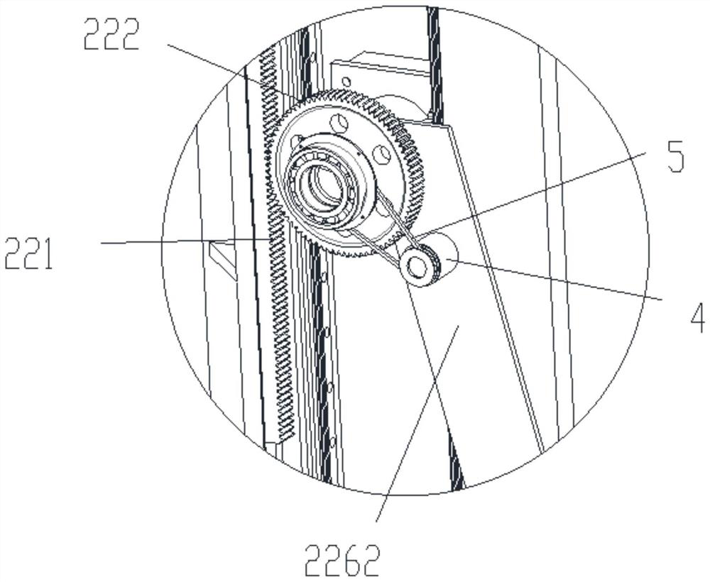
The invention relates to the technical field of non-woven fabric membrane materials and spinning and papermaking membrane materials, in particular to a constant-tension dancing roller control device. The constant-tension dancing roller control device comprises a supporting assembly and an adjusting assembly, the adjusting assembly is arranged on the supporting assembly and comprises a balance arm assembly, a lifting assembly and an angle sensor, the balance arm assembly is rotationally connected with the supporting assembly, and the angle sensor is used for obtaining rotation information of the balance arm assembly and controlling the lifting assembly to drive the balance arm assembly to move in the vertical direction, so that the balance arm assembly is located at the balance position. The film material is wound on a guide roller, the tension of the film material is determined according to the set tension of an air cylinder, and the change of the tension is shown on the rotating angle of the balance arm assembly, so that the balance arm assembly is conveniently controlled to ascend and descend through the lifting assembly, the constant tension of the film material is achieved, the movement range of the tension dancing roller is large, and the adjusting distance is long; and the device is particularly suitable for a high-speed film material production line, and the practicability and the tension control efficiency are improved.

Description

technical field [0001] The invention relates to the technical field of non-woven film material and textile and papermaking film material, in particular to a constant tension dancing roller control device. Background technique [0002] Due to the speed difference between the tension roller speed and the unwinding speed of the tension adjustment device in the prior art, in order to avoid the product from being pulled, broken or uneven, it is necessary to adjust the tension. In the prior art, a balance swing arm is often set to adjust the product. The tension during unwinding, but in the actual production process, when the speed difference exceeds the preset value, the balance swing arm will swing, because the film material provided by the swing alone has little room for adjustment, it is not suitable for high-speed production lines, and it is easy to reach the upper limit and get stuck If it is stuck, the entire unwinding system needs to be adjusted accordingly. The workload o...

Claims


Application Information

Patent Timeline
Patent Type & Authority Applications(China)
IPC IPC(8): B65H23/185B65H23/26B65H26/04
CPCB65H23/185B65H23/1825B65H23/26B65H26/04B65H2701/174Y02P70/50
Inventor 王至昶钱亚超
Owner CHANGZHOU RUISAI ELECTROMECHANICAL EQUIP CO LTD
Learn More