
Workpiece cleaning device for mechanical equipment machining and using method of workpiece cleaning device

A technology of mechanical equipment and cleaning devices, which is applied in the direction of cleaning methods using tools, cleaning methods using liquids, cleaning methods and utensils, and can solve the problems of wasting cleaning fluid, reducing cleaning quality, and increasing cleaning time, etc.

Inactive Publication Date: 2021-05-11
杭州富阳正茂进出口有限公司
View PDF10 Cites 3 Cited by
  • Summary
  • Abstract
  • Description
  • Claims
  • Application Information

AI Technical Summary

Problems solved by technology

[0004] The following problems still exist in the above-mentioned documents: 1. The workpiece is cleaned only by soaking or rinsing, and the workpiece is in a static state during cleaning, so that the impurities on the surface of the workpiece cannot be thoroughly cleaned; 2. Traditional simple rinsing or soaking cannot remove impurities on the workpiece at the same time, and subsequent cleaning is required, which increases the cleaning time and reduces the cleaning efficiency; 3. When the traditional method of rinsing is used to clean the workpiece, if the nozzle When the pressure is insufficient, it is easy to cause waste of cleaning fluid, and the cleaning task cannot be completed accurately, thereby reducing the quality of cleaning

Method used


Image

  • Workpiece cleaning device for mechanical equipment machining and using method of workpiece cleaning device
  • Workpiece cleaning device for mechanical equipment machining and using method of workpiece cleaning device
  • Workpiece cleaning device for mechanical equipment machining and using method of workpiece cleaning device

Examples


Embodiment

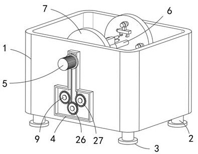
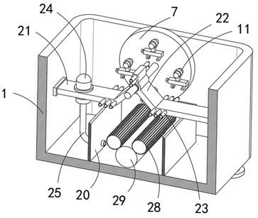
[0034] refer to Figure 1-7 , a workpiece cleaning device for mechanical equipment processing, comprising a cleaning housing 1, the lower end of the cleaning housing 1 is evenly connected with four vertical pillars 2, and the lower ends of the pillars 2 are fixedly connected with a ground-contact base 3, cleaning The side wall of the housing 1 is fixedly connected with a "convex" shaped casing 4, the side wall of the casing 4 is fixedly connected with a drive motor 5, and the output end of the drive motor 5 is fixedly connected with a first rotating shaft 6, and the first rotating shaft 6 is away from the One end of the drive motor 5 penetrates the shell 4 and is connected to the inner wall of the cleaning housing 1 in rotation. The outer wall of the first rotating shaft 6 in the cleaning housing 1 is fixedly sleeved with two vertical discs 7, and the two discs 7. A plurality of workpiece suspension mechanisms are provided on the opposite side walls. The workpiece suspension m...


PUM


Abstract

The invention belongs to the technical field of workpiece cleaning, and particularly relates to a workpiece cleaning device for mechanical equipment machining and a using method of the workpiece cleaning device. The workpiece cleaning device comprises a cleaning shell, four vertical supporting columns are evenly distributed and connected to the lower end of the cleaning shell, and the lower ends of the supporting columns are fixedly connected with a base making contact with the ground. An inverted-T-shaped shell is fixedly connected to the side wall of the cleaning shell, a driving motor is fixedly connected to the side wall of the shell, a first rotating shaft is fixedly connected to the output end of the driving motor, and the end, away from the driving motor, of the first rotating shaft penetrates through the shell and is rotationally connected with the inner wall of the cleaning shell. Two vertical discs fixedly sleeve the outer side wall of the first rotating shaft in the cleaning shell. The workpiece cleaning device for mechanical equipment machining and the using method of the workpiece cleaning device have the advantages that a plurality of workpieces can do circular motion to replace a traditional static cleaning mode, the surfaces of the workpieces can be further cleaned through reverse rotation of two cleaning rollers, in addition, the workpieces are flushed in a circulating mode, and the workpiece cleaning effect can be further improved.

Description

technical field [0001] The invention relates to the technical field of workpiece cleaning, in particular to a workpiece cleaning device for mechanical equipment processing. Background technique [0002] The cleaning machine is a device that replaces manual cleaning of the surface of the workpiece by mechanical means. It is mainly used to clean chips, oil, wax, oxide layers, etc. on the surface of the workpiece. In the production process of industrial machinery and electronic products, the cleanliness of the workpiece surface requires Gradually improving, the design and use of cleaning equipment are increasingly valued by manufacturers. During the processing of metal workpieces, workpieces need to be cleaned. [0003] For example, a mechanical device for cleaning workpieces in my country's patent application number CN201710035943.1, including a moving seat, a clamping device, a workpiece, a fixed bracket, a motor 1, a rotating seat, an oil cylinder, a turning seat 1, a connec...

Claims


Application Information

Patent Timeline
IPC IPC(8): B08B1/02B08B3/02B08B3/14B08B13/00
CPCB08B3/022B08B3/14B08B13/00B08B1/20
Inventor 蒋学政
Owner 杭州富阳正茂进出口有限公司
Learn More