Intelligent body builder for upper limb exercise
A kind of fitness equipment, intelligent technology, applied in the field of fitness equipment, can solve the problems that users of different heights cannot exercise, can not meet the fitness needs, and the fitness function is single, and achieve the effect of complete functions, small limitations, and convenient operation
- Summary
- Abstract
- Description
- Claims
- Application Information
AI Technical Summary
Problems solved by technology
Method used
Image
Examples
Embodiment 1
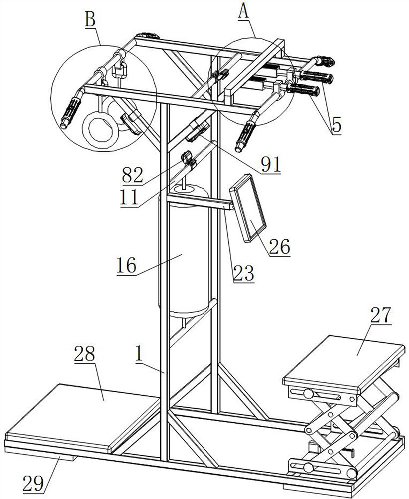
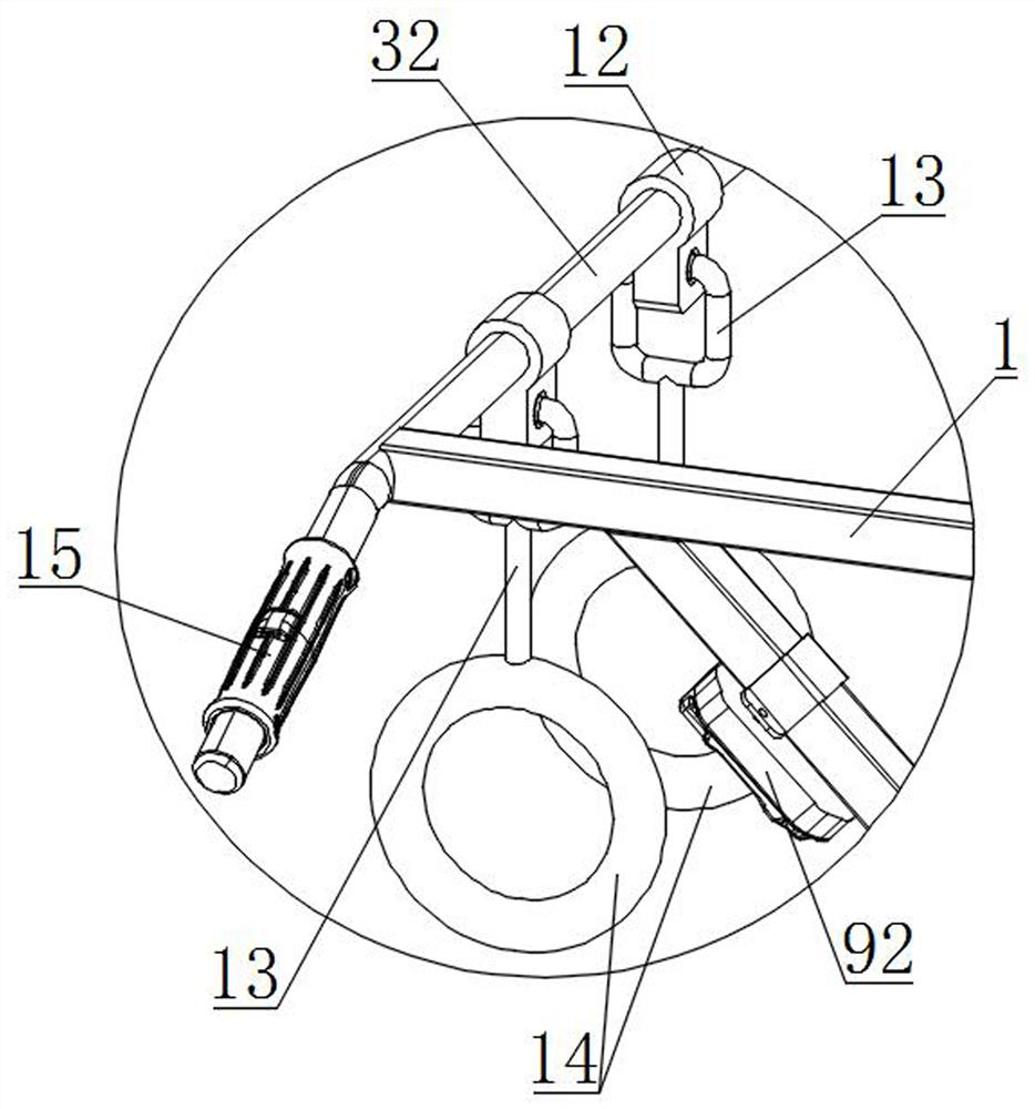
[0032] The main structure of this embodiment, such as Figure 1~6 As shown, the present invention proposes an intelligent fitness device for upper limb exercise, including a support frame 1, a limit frame 2, a first connecting rod 31, a second connecting rod 32, a standing platform 27, a pull-up assembly, and a suspension ring Components and touch display mechanisms;
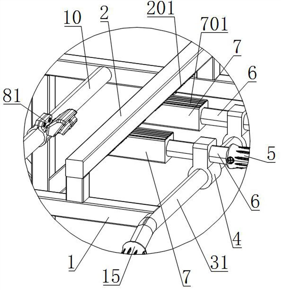
[0033]The limit frame 2 is an inverted U-shaped rod-shaped structure, the limit frame 2 is arranged on the top of the support frame 1, and the first connecting rod 31 and the second connecting rod 32 are respectively arranged at the two ends of the top of the support frame 1; There are two groups of components arranged side by side in the longitudinal direction. The pull-up component includes a rotating table 4, a first handle 5, a fixed rod 6 and a limit post 7. The rotating table 4 is slidably arranged on the first connecting rod 31, and the two ends of the fixed rod 6 are respectively It is connected with th...
Embodiment 2
[0036] On the basis of the above-mentioned embodiments, this embodiment further defines the structure of the spacer 2, such as Figure 1~6 As shown, the bottom of the inside of the limiting frame 2 is provided with a first clamping strip 201, the length direction of the first clamping strip 201 is arranged horizontally, and a plurality of first clamping strips 201 are arranged side by side along the longitudinal direction. A clamping slot is formed between one clamping strip 201; a plurality of second clamping strips 701 for clamping into the clamping slot are arranged side by side on the top surface of the limiting post 7 along the longitudinal direction. When adjusting the distance between the two first handles 5, first turn the limit post 7 downward from the limit frame 2, then slide the turntable 4 longitudinally, and then snap the second clip 701 into the slot there , can further improve the reliability of the snap-fitting, and prevent the first handle 5 from slipping whe...
Embodiment 3
[0038] On the basis of the above-mentioned embodiments, this embodiment further defines the structures of the first clamping strip 201 and the second clamping strip 701. As shown in 6, the longitudinal ends of the bottom of the first clamping strip 201 are provided with first For chamfering, second chamfering is provided at both longitudinal ends of the top of the second clip bar 701 . By setting the first chamfer and the second chamfer, it is convenient to snap the second clip bar 701 into the clip slot. Other parts of this embodiment are the same as those of the foregoing embodiment, and will not be repeated here.
PUM
 Abstract
Description
Claims
Application Information
 - R&D Engineer
- R&D Manager
- IP Professional
- Industry Leading Data Capabilities
- Powerful AI technology
- Patent DNA Extraction
Browse by: Latest US Patents, China's latest patents, Technical Efficacy Thesaurus, Application Domain, Technology Topic, Popular Technical Reports.
© 2024 PatSnap. All rights reserved.Legal|Privacy policy|Modern Slavery Act Transparency Statement|Sitemap|About US| Contact US: help@patsnap.com


