
Curve fiber composite structure aeroelasticity optimization method considering local buckling

A kind of aeroelasticity, fiber technology, applied in design optimization/simulation, instrument, geometric CAD, etc., can solve the problems of deviation of analysis results, lack of reference significance of analysis results, and inability to use automatic optimization programs.

Active Publication Date: 2021-05-07
BEIHANG UNIV
View PDF4 Cites 1 Cited by
  • Summary
  • Abstract
  • Description
  • Claims
  • Application Information

AI Technical Summary

Problems solved by technology

[0005] At present, the research on curve fiber optimization technology at home and abroad has the following deficiencies: Because the buckling analysis of the complex real wing model cannot effectively avoid the local buckling mode of the non-focused part, it is difficult to automatically obtain the buckling mode information of the concerned part, so not available for auto optimizer
[0006] However, most of the buckling analysis methods mentioned in the prior art are based on two ideas: one is to extract local elements and simplify them into four-sided simply supported composite material plates for buckling analysis, but the actual boundary of the object extracted by this method There is a large deviation between the conditions and the real structure, and the analysis results have no reference significance; another way of thinking is to stiffen the rest of the parts and only keep the parts of interest, but this method will greatly destroy the force transmission route of the original structure, so the analysis results have great significance. big deviation

Method used


Image

  • Curve fiber composite structure aeroelasticity optimization method considering local buckling
  • Curve fiber composite structure aeroelasticity optimization method considering local buckling
  • Curve fiber composite structure aeroelasticity optimization method considering local buckling

Examples


Embodiment Construction

[0061] In order to facilitate those of ordinary skill in the art to understand and implement the present invention, the present invention will be further described in detail and in-depth below in conjunction with the accompanying drawings.

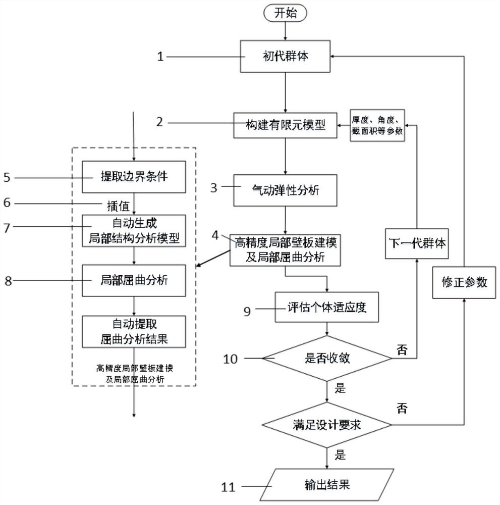
[0062] The present invention is a double-layer optimization algorithm suitable for the aeroelastic tailoring of curved fiber composite airfoil structures, such as figure 1 As shown, considering the calculation efficiency and analysis accuracy at the same time, the overall wing model with medium density mesh is used to analyze the aeroelastic parameters, such as static deformation, flutter velocity and composite failure, etc.; The panel model performs local buckling analysis of the airfoil to accurately analyze and predict the local buckling characteristics of the structure. The boundary conditions of the local buckling analysis are based on the static aeroelastic analysis results. Due to the different grid densities, an appropriate interpo...


PUM


Abstract

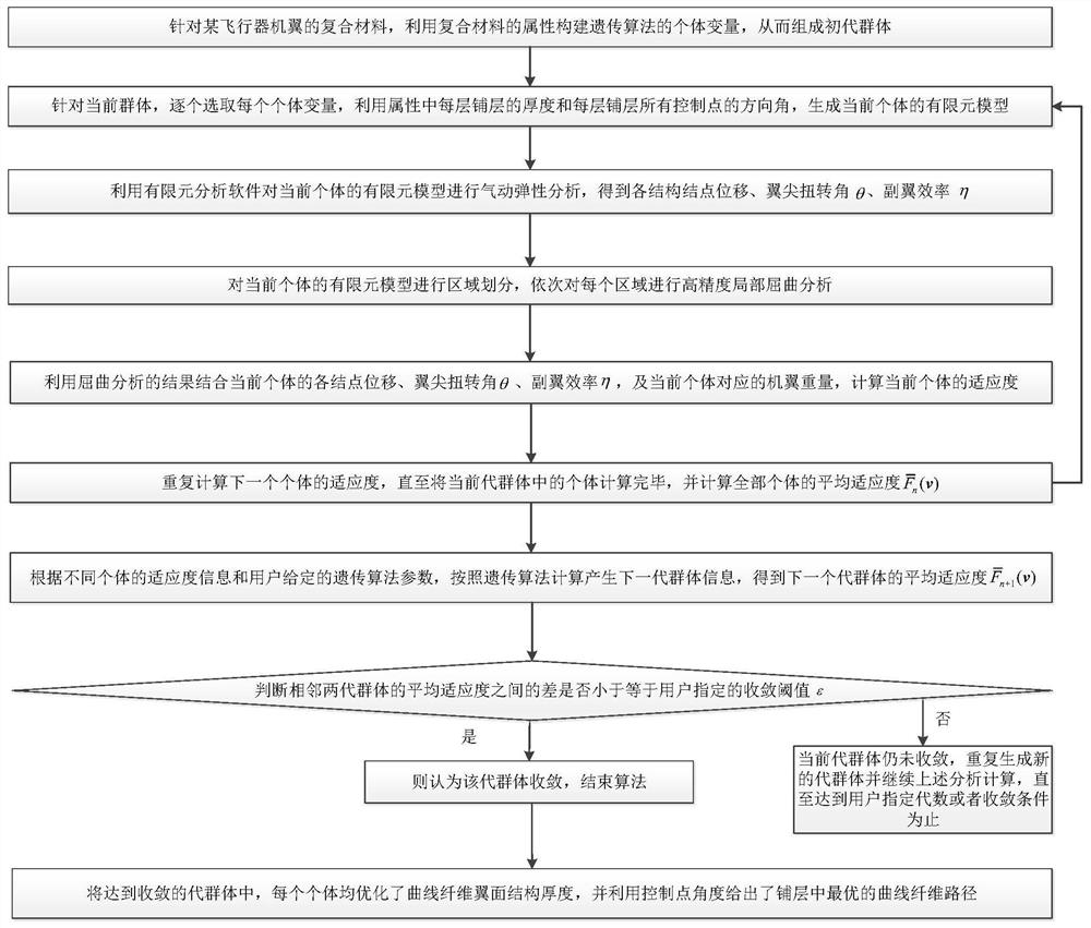
The invention discloses a curve fiber composite material structure aeroelasticity optimization method considering local buckling, and belongs to the field of composite material elasticity optimization. The method comprises the following steps: firstly, constructing individual variables by utilizing attributes of an aircraft wing composite material to form a primary group; then, selecting individuals one by one to generate a finite element model; performing aeroelasticity analysis to obtain elasticity analysis parameters; carrying out region division and carrying out high-precision local buckling analysis; calculating the fitness of the current individual by combining the buckling analysis result with the elastic analysis parameters and the wing weight, repeatedly calculating the fitness of all individuals, and then calculating the average fitness; then, generating a next generation group, and calculating average fitness; enabling the group of the generation to converge until the difference between two adjacent average fitness is smaller than or equal to a convergence threshold value; and optimizing the thickness of the curve fiber airfoil structure for each individual, and giving the optimal path in the laying layer by using the angle of a control point. According to the method, curve fiber design can be automatically carried out on the wing model.

Description

technical field [0001] The invention belongs to the field of elastic optimization of composite materials, in particular to an aeroelastic optimization method for curved fiber composite structures considering local buckling. Background technique [0002] Composite laminates have significant weight advantages and are already widely used in modern aircraft. Traditional linear fiber composite laminates are prone to instability and failure when subjected to in-plane compression and shear loads, and their performance advantages cannot be fully utilized. [0003] Curved fiber composite laminates are a new form of composite material in recent years. Compared with traditional linear fiber composite materials, the fiber laying angle is not limited, the cutting design space is large, and the advantage of weight reduction is obvious, and it is limited by in-plane shear. The tangential buckling instability characteristic has great advantages. However, the analysis of this structure is ...

Claims


Application Information

Patent Timeline
Patent Type & Authority Applications(China)
IPC IPC(8): G06F30/15G06F30/27G06F30/23G06F113/26
CPCG06F30/15G06F30/27G06F30/23G06F2113/26Y02T90/00
Inventor 万志强王泽溪王晓喆杨超
Owner BEIHANG UNIV
Learn More