
A Highly Integrated Crankcase Ventilation Separation Device

A crankcase ventilation and separation device technology, applied in crankcase ventilation, machine/engine, mechanical equipment, etc., can solve the problems of difficult removal, long blow-by gas circulation paths, threats to the engine lubrication system, etc., to simplify the layout of parts, simplify the Design complexity, the effect of reducing the risk of oil emulsification

Active Publication Date: 2022-02-08
DONGFENG COMML VEHICLE CO LTD
View PDF4 Cites 0 Cited by
  • Summary
  • Abstract
  • Description
  • Claims
  • Application Information

AI Technical Summary

Problems solved by technology

In cold regions, the temperature of the piston blow-by gas will drop during the flow process, and once it reaches the freezing point, liquid water will be precipitated, and the liquid water produced will mix with the liquid engine oil particles generated by the splash of the engine, which will easily produce an oil emulsion. Generally, it is milky white or light brown. It is not easy to remove after it is produced. It will pose a serious threat to the engine lubrication system if it accumulates for a long time.
[0009] In the existing design of the crankcase ventilation system, the blow-by gas has a long circulation path, and the thin-walled shell parts such as the flywheel housing and the cylinder head cover that come into contact with during the flow process are all parts of the engine where the temperature is relatively low, so the blow-by gas is very easy to pass through. Condensation on the surface; the external long pipeline is also a part of the engine with a lower temperature

Method used


Image

  • A Highly Integrated Crankcase Ventilation Separation Device
  • A Highly Integrated Crankcase Ventilation Separation Device
  • A Highly Integrated Crankcase Ventilation Separation Device

Examples


Embodiment Construction

[0029] The present invention will be further described in detail below in conjunction with the accompanying drawings and specific embodiments to facilitate a clear understanding of the present invention, but they do not limit the present invention.

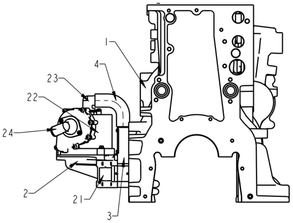
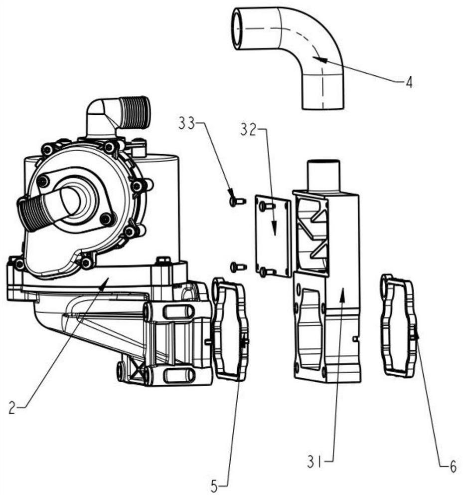
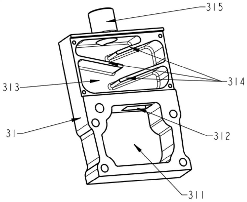
[0030] Such as Figure 1-3 As shown, the present invention includes a fine separation device 2 and a rough separation device 3, and the fine separation device 2 communicates with the rough separation device 3 through a pipeline 4; the rough separation device 3 includes a rough separation device body 31, and the rough separation device 3 The device body 31 includes an upper chamber and a lower chamber, the lower chamber is provided with a cylinder air intake port 311, and the upper chamber is provided with a separation labyrinth cavity 313, and the upper chamber and the lower chamber are communicated through the coarse separation device air intake port 312, so The air outlet 315 of the coarse separation device is opened on the top ...


PUM


Abstract

The invention discloses a highly integrated crankcase ventilation separation device. It includes a fine separation device and a rough separation device, and the fine separation device communicates with the rough separation device through a pipeline; the rough separation device includes a rough separation device body, and the rough separation device body includes an upper chamber and a lower chamber. The lower chamber is provided with an air intake port of the cylinder body, the upper chamber is provided with a separation labyrinth cavity, the upper chamber and the lower chamber are connected through the air intake port of the coarse separation device, and the top of the upper chamber is provided with an air outlet port of the coarse separation device. The fine separation device, the coarse separation device and the connecting pipeline of the present invention jointly form a highly integrated crankcase ventilation separation device. Piston blow-by gas is directly drawn from the cylinder body, the passage of blow-by gas is greatly shortened, the temperature drop of blow-by gas during circulation is reduced, and the risk of water vapor condensation and the resulting risk of oil emulsification are greatly reduced.

Description

technical field [0001] The invention belongs to the technical field of engine crankcase ventilation systems, and in particular relates to a highly integrated crankcase ventilation separation device. Background technique [0002] With the upgrading of emission regulations, the control of engine crankcase emissions is becoming more and more stringent. The crankcase ventilation system of the National VI stage medium and heavy-duty engines generally adopts two-stage separation, including coarse separation and fine separation, to separate the piston blow-by gas. To reduce engine oil consumption and reduce pollution to the atmosphere or the pressure end of the supercharger. [0003] The coarse separation device generally adopts the integrated design of the cylinder head cover, and also adopts the integrated design of the flywheel housing, or directly adopts the external design form. The gas movement direction and the oil return direction in the coarse separation device are general...

Claims


Application Information

Patent Timeline
Patent Type & Authority Patents(China)
IPC IPC(8): F01M13/04F01M13/00
CPCF01M13/04F01M13/00F01M2013/0461
Inventor 苏振兴陈功军邓学勤王必璠徐敏胡晶晶
Owner DONGFENG COMML VEHICLE CO LTD
Learn More