Horizontal swing type shock insulation support with beam falling prevention function
A technology of seismic isolation bearing and anti-drop beam, which is applied to bridges, bridge parts, bridge materials, etc., can solve the problems of seismic isolation of the upper and lower structures of the building, unreasonable restrictions on multi-directional movable bearings, etc., and achieves low construction cost. , easy replacement and maintenance, energy reduction effect
- Summary
- Abstract
- Description
- Claims
- Application Information
AI Technical Summary
Problems solved by technology
Method used
Image
Examples
Embodiment 1
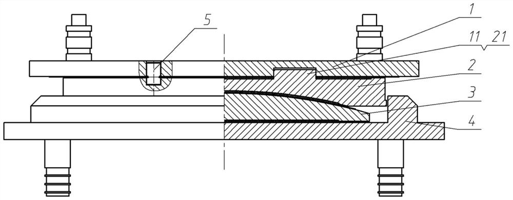
[0027] Such as figure 1 , 2 The shown shock-absorbing support includes, from top to bottom, an upper slide plate 1, an upper support plate 2, a spherical crown liner 3 and a lower support plate 4; the lower surface of the upper support plate 2 is provided with The spherical crown liner 3 is a spherical concave surface matching the spherical crown surface; the lower support plate 4 is provided with a groove, and the spherical crown liner 3 and the upper support plate 2 are both located in the groove. The groove on the lower support plate 4 is circular.
[0028] There are sliding friction pairs between the upper sliding plate 1 and the upper bearing plate 2, between the upper bearing plate 2 and the spherical crown lining plate 3, between the spherical crown lining plate 3 and the lower bearing plate 4, and No silicone grease lubrication. The above-mentioned sliding friction pair is as follows:
[0029] The lower surface of the upper sliding plate 1 is provided with a stainl...
Embodiment 2
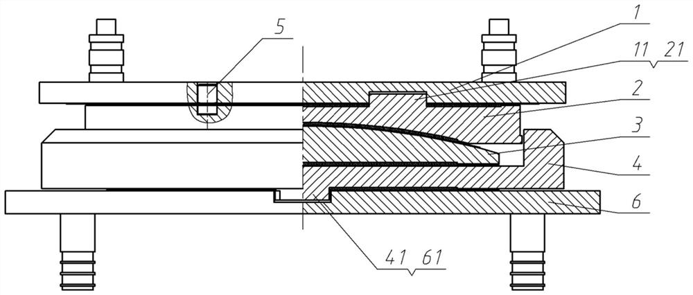
[0036] Such as image 3 , 4 Compared with the shock-absorbing support in Embodiment 1, the shown shock-absorbing support adds a lower sliding plate 6, and the lower sliding plate 6 is located below the lower supporting plate 4; the upper surface of the lower sliding plate 6 A stainless steel plate is provided, and a wear-resistant plate is provided on the lower surface of the lower support plate 4, and the wear-resistant plate and the stainless steel plate form a sliding friction pair.
[0037] The upper surface of the lower sliding plate 6 is provided with a rail groove 61, and the lower surface of the lower support plate 4 is provided with a sliding rail 41, and the sliding rail 41 and the rail groove 61 are slidably matched to form a sliding rail mechanism. A sliding friction pair formed by a wear-resistant plate and a stainless steel plate is also provided between the side walls of the groove 61 . The sliding guide rail 41 is arranged along the vertical bridge direction ...
Embodiment 3
[0040] Such as Figure 5 , 6 In the shown shock-isolation bearing, the shear pin 5 is omitted on the basis of the first embodiment.
[0041] When the bearing is displaced within the design value, since the upper bearing plate 2 and the upper sliding plate 1 can rotate and swing, the bearing is equivalent to the ordinary multi-directional bearing; when the bearing is impacted by earthquakes, etc., The circular tenon 21 is limited by the circular sinking groove 11, and the relative displacement of the upper sliding plate 1 and the lower bearing plate 4 cannot exceed the radius of rotation of the bearing, which prevents the excessive displacement of the upper and lower structures of the bridge (or building) from causing permanent damage. damage, the bearing is equivalent to the limit type multi-directional bearing at this time.
[0042] Such as Figure 7 As shown, the layout of the seismic isolation bearing of the present invention applied in the bridge, the upper left is the se...
PUM
 Abstract
Description
Claims
Application Information
 - Generate Ideas
- Intellectual Property
- Life Sciences
- Materials
- Tech Scout
- Unparalleled Data Quality
- Higher Quality Content
- 60% Fewer Hallucinations
Browse by: Latest US Patents, China's latest patents, Technical Efficacy Thesaurus, Application Domain, Technology Topic, Popular Technical Reports.
© 2025 PatSnap. All rights reserved.Legal|Privacy policy|Modern Slavery Act Transparency Statement|Sitemap|About US| Contact US: help@patsnap.com


