
Image detection system of transportation tool

A transportation tool and image technology, applied in the field of image detection system, can solve the problem of distance deviation of detected objects

Inactive Publication Date: 2021-05-07
陈娅雄
View PDF8 Cites 1 Cited by
  • Summary
  • Abstract
  • Description
  • Claims
  • Application Information

AI Technical Summary

Problems solved by technology

[0003] Based on the above-mentioned discovery by the inventors, the existing image detection system of a transportation tool mainly has the following deficiencies, such as: when the car is running, the temperature inside the compartment is affected by the engine, and the air inside When it touches the end face of the detector, condensation will condense into small water droplets, so that the end face of the detector will be attached with small water droplets, causing the detector to be affected by the water droplets and the distance of the detected object will be deviated.

Method used


Image

  • Image detection system of transportation tool
  • Image detection system of transportation tool
  • Image detection system of transportation tool

Examples


Embodiment 1

[0026] Example 1: Please refer to Figure 1-Figure 5 , the specific embodiments of the present invention are as follows:

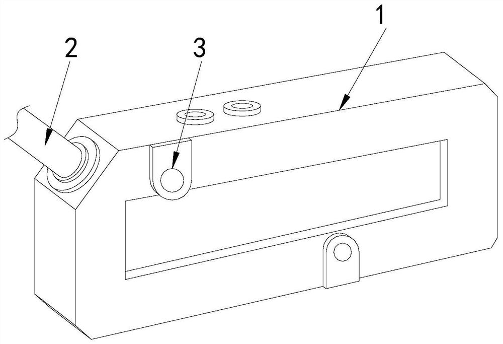
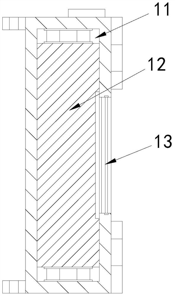
[0027] Its structure includes a main body 1, a connecting line 2, and a mounting seat 3. The top side of the main body 1 is connected with a connecting line 2. There are two mounting seats 3 located at the front end of the main body 1. The main body 1 includes The installation groove 11, the detector 12, and the detection port 13, the installation groove 11 is arranged inside the main body 1, the detector 12 is installed in the installation groove 11, and the detection port 13 is located at the front end of the main body 1 , and engage with the detector 12 .

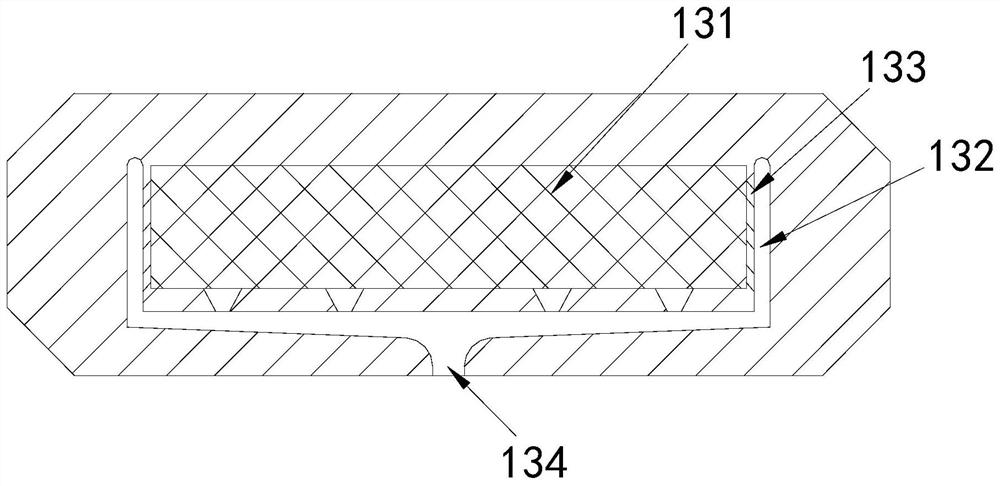
[0028] The detection port 13 includes an attached water net 131, a water channel 132, a drainage channel 133, and a water outlet 134. The attached water net 131 is installed laterally on the end face of the detection port 13, and the water channel 132 is arranged at the detection port. 13, the drai...

Embodiment 2

[0032] Example 2: Please refer to Figure 6-Figure 8 , the specific embodiments of the present invention are as follows:

[0033] The flow tank a31 includes a raised block b1, a water storage tank b2, and a guide plate b3. The raised block b1 is arranged at the bottom end of the flow tank a31, and the water storage tank b2 is located at the lower end of the raised block b1. The plate b3 is embedded in the bottom of the water storage tank b2, and the end surface of the water storage tank b2 is arc-shaped, which is beneficial to concentrate the water droplets through the water storage tank b2, and then guide the water droplets downward through the guide plate b3.

[0034] The guide plate b3 includes a mounting seat b31, an embedding block b32, and a deflector b33. The top end of the mounting seat b31 is embedded with an embedding block b32, and the embedding block b32 is connected to the bottom of the water storage tank b2. There are seven baffles b33, which are arranged horizo...


PUM


Abstract

The invention discloses an image detection system of a transportation tool. The image detection system structurally comprises a main body, a connecting line and two mounting seats, the side end of the top of the main body is connected with the connecting line, the two mounting seats are located at the front end of the main body, the main body comprises a mounting groove, a detector and a detection opening, the detection opening comprises a water attachment net, a water passing groove, a water drainage groove and a water drainage opening, the drainage groove comprises a groove body, a guide block and a flow guide plate, the flow guide plate comprises a flowing groove, a siphon groove, a flow guide groove and a fixing block, the water attaching net is installed in the detection opening, the drainage groove is connected with the side end of the water attaching net, water drops can flow into the drainage groove in a concentrated mode, and therefore water flow can be drained outwards in a concentrated mode, water flow attached to the end face of the water attaching net is prevented from flowing randomly, and it is guaranteed that the detector can accurately detect the distance between the detector and an object.

Description

technical field [0001] The invention relates to the field of transportation, in particular to an image detection system of a transportation tool. Background technique [0002] The image detection system of the transportation tool is installed on the four corners of the car to detect the objects next to the car. If the distance between the car and the object is too close, the detector detects it and transmits it to the display of the car. An alarm is given on the screen to remind the driver that the car is close to the object, avoiding the situation where the car is degraded to the object or pedestrians, and has high safety performance. [0003] Based on the above-mentioned discovery by the present inventors, the existing image detection system of a transportation tool mainly has the following deficiencies, such as: when the car is running, the temperature inside the compartment is affected by the engine, and the temperature of the inside air is relatively high. When it touc...

Claims


Application Information

Patent Timeline
Patent Type & Authority Applications(China)
IPC IPC(8): B60R21/013B60R11/00
CPCB60R21/013B60R11/00B60R2011/0042
Inventor 刘福彬
Owner 陈娅雄
Learn More