Clamping device for printed circuit board (PCB) code spraying

A technology of PCB board and clamping device, which is applied in the field of clamping device for PCB printing, can solve the problems of unadjustable position of printed circuit board, inconvenient acquisition of printing codes of different shapes, inconvenience of printing codes, etc., to improve flexibility Sexuality, easy clamping, quality assurance effect

Inactive Publication Date: 2021-05-07
上海潜利智能科技有限公司
View PDF23 Cites 1 Cited by
  • Summary
  • Abstract
  • Description
  • Claims
  • Application Information

AI Technical Summary

Problems solved by technology

Printed circuit boards need to be coded during the production process to facilitate identification, and the printed circuit board needs to be clamped and fixed when spraying codes. The existing clamping device needs to occupy too much printing space when clamping. The circuit board area makes it inconvenient to spray codes, and the position of the printed circuit board cannot be adjusted during the printing process, which is not convenient to obtain different shapes of inkjet codes; therefore, it is necessary to improve the existing technology

Method used


Image

  • Clamping device for printed circuit board (PCB) code spraying
  • Clamping device for printed circuit board (PCB) code spraying
  • Clamping device for printed circuit board (PCB) code spraying

Examples


Embodiment 1

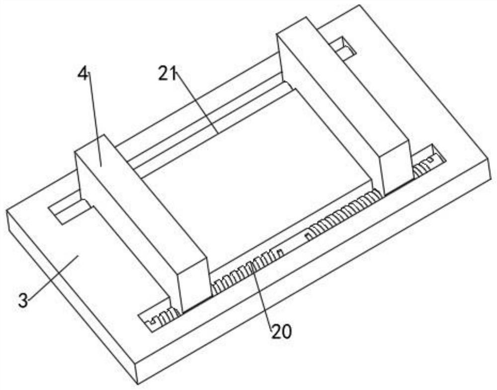
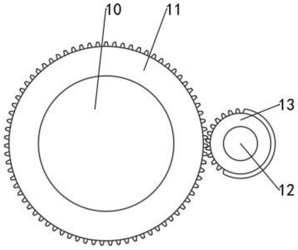
[0020] see Figure 1-4 , a clamping device for PCB board printing, including a base 1, a mounting seat 3 is movably connected to the base 1 via a substrate 2, and two limiting seats 4 are arranged at intervals on the mounting seat 3, and the limiting seat 4 passes through The mounting shaft 16 is connected with a base 17; the inner side of the base 17 is provided with a mounting plate 22 and a fixed seat 24 at intervals, and several horizontal hydraulic telescopic rods 23 are evenly installed between the mounting plate 22 and the base 17, and the mounting plate 22 Two driving rods 27 are connected to the side away from the hydraulic telescopic rod 23 in rotation. The corresponding limit rod 25 is rotationally connected. One end of the limit rod 25 extends to the outside of the base 17 and is equipped with a limit block 26. The hydraulic telescopic rod 23 drives the mounting plate 22 to move straight. Under the transmission action of the drive rod 27 The two limit rods 25 are ...

Embodiment 2

[0029] In order to facilitate the installation and fixation of the clamping device, this embodiment is improved on the basis of Embodiment 1. The improvement is that: the base 1 is evenly arranged with a number of through threaded holes, so that bolts can be used to fix the clamping device. The above-mentioned clamping device is assembled and fixed, and the operation is convenient.


PUM


Abstract

The invention discloses a clamping device for printed circuit board (PCB) code spraying. The device comprises a base, wherein the base is movably connected with a mounting seat through a substrate, two limiting seats are arranged on the mounting seat at intervals, and the limiting seats are connected with a base through a mounting shaft; according to the clamping device for PCB code spraying, the two limiting blocks are controlled to be unfolded or folded through a hydraulic telescopic rod, the PCB can be conveniently clamped, it is only needed to occupy a very small clamping area needs, so that it is convenient to spray; by meshing a worm gear with a worm, the PCB can be conveniently driven to be turned over integrally, and a gear motor drives a driving shaft and an assembling shaft to conduct transmission, so that a PVB board operates intermittently, sprayed codes of different shapes can be conveniently obtained, and the machining flexibility is improved; the initial distance between the two limiting seats can be conveniently adjusted through an adjusting lead screw, so that is convenient to clamp the PCB; in addition, a buffer structure is arranged between a base and the base plate, so that the vibration impact of the clamping device during operation is effectively reduced, and the code spraying quality is ensured.

Description

technical field [0001] The invention relates to the field of PCB board production, in particular to a clamping device for coding on a PCB board. Background technique [0002] The Chinese name of PCB is printed circuit board, also known as printed circuit board, which is an important electronic component, a support for electronic components, and a carrier for electrical connections of electronic components; Known as "printed" circuit boards, printed boards have evolved from single-layer to double-sided, multi-layer and flexible, and still maintain their own development trends. Due to the continuous development in the direction of high precision, high density and high reliability, continuous reduction in size, cost reduction and performance improvement, printed boards still maintain strong vitality in the development of future electronic equipment. Printed circuit boards need to be coded during the production process to facilitate identification, and the printed circuit board...

Claims


Application Information

Patent Timeline
Patent Type & Authority Applications(China)
IPC IPC(8): B41J3/407B41J29/00F16F15/067
CPCB41J3/4073B41J29/00F16F15/067
Inventor 沈龙刘明星李军张胜
Owner 上海潜利智能科技有限公司
Why Eureka
Try Eureka