Quantitative shaping device for manufacturing LED illuminating lamp

A technology of LED lighting and U-shaped slot, applied in the field of LED lighting, can solve the problems of increasing product defect rate, different LED lamp specifications, waste of resources, etc., to achieve rational utilization, avoid inconsistent specifications, and reduce defects rate effect

Inactive Publication Date: 2021-05-07
吉文娟
View PDF0 Cites 1 Cited by
  • Summary
  • Abstract
  • Description
  • Claims
  • Application Information

AI Technical Summary

Problems solved by technology

[0002] The LED light is an electroluminescent semiconductor material chip, which is cured on the bracket with silver glue or white glue, and then connected to the chip and the circuit board with silver or gold wires. During production and manufacturing, it is necessary to ensure that the amount of raw materials injected is constant to ensure the quality of the product. The existing molding device has a large error in injecting raw materials, resulting in different product specifications.
[0003] When LED lamps are mass-produced, the existing shaping devices often use the method of manually opening the valve when injecting raw materials. However, the way of manually opening the valve will produce large errors, which will cause changes in the amount of raw materials injected before and after. As a result, the specifications of the LED lamps produced are different. Too much raw material injection will lead to waste of resources, and too little raw material injection will lead to product deformation and increase the defective rate of the product.

Method used


Image

  • Quantitative shaping device for manufacturing LED illuminating lamp
  • Quantitative shaping device for manufacturing LED illuminating lamp
  • Quantitative shaping device for manufacturing LED illuminating lamp

Examples


Embodiment Construction

[0024] The following will clearly and completely describe the technical solutions in the embodiments of the present invention with reference to the accompanying drawings in the embodiments of the present invention. Obviously, the described embodiments are only some, not all, embodiments of the present invention. Based on the embodiments of the present invention, all other embodiments obtained by persons of ordinary skill in the art without making creative efforts belong to the protection scope of the present invention.

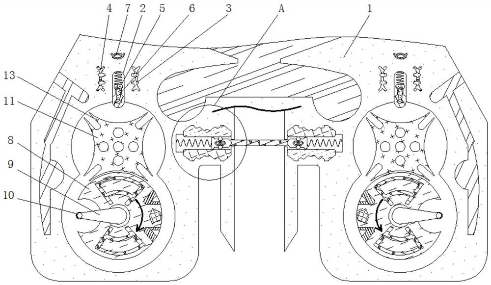
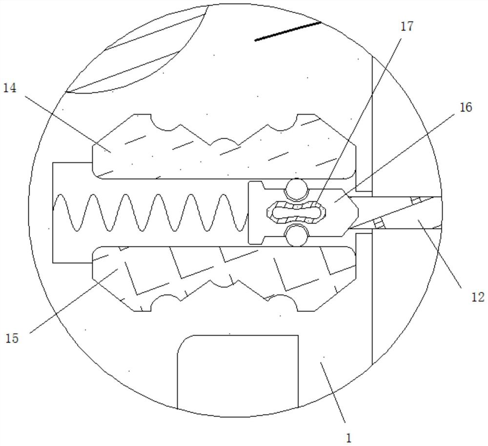
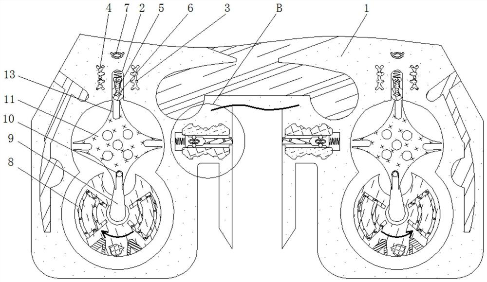
[0025] see Figure 1-4 , a quantitative shaping device for the manufacture of LED lighting lamps, including a housing 1, the inner wall of the housing 1 is provided with a chute 2, the inner wall of the chute 2 is movably connected with a slider 5, and the material of the slider 5 is rubber Material, the slider 5 is closely attached to the inner wall of the chute 2, the slider 5 plays the role of sliding, the inner wall of the slider 5 is fixedly connected wit...


PUM


Abstract

The invention relates to the technical field of LED lighting, and discloses a quantitative shaping device for manufacturing an LED lighting lamp. The quantitative shaping device comprises a shell, the inner wall of the shell is provided with a sliding groove, the inner wall of the sliding groove is movably connected with a sliding block, the inner wall of the sliding block is fixedly connected with a dielectric plate, a positive plate is fixedly connected to the inner wall, close to the outer side of the sliding groove, of the shell, a negative plate is fixedly connected to the inner wall, close to the outer side of the sliding groove, of the shell, and a piezoresistor is fixedly connected to the inner wall, close to the outer side of the sliding groove, of the shell. According to the quantitative shaping device for manufacturing the LED illuminating lamp, a rotating shaft drives a driven disc to rotate, the manner that a valve is opened through manual cooperation is avoided, larger errors are prevented from being generated, the situation that the injection amount of raw materials before and after injection changes is avoided, the situation that produced LED lamps are different in specification is avoided, and the situation that resources are wasted due to the fact that too much raw materials are injected is avoided; and product deformation caused by too little raw material injection is avoided, and the defective rate of products is reduced.

Description

technical field [0001] The invention relates to the technical field of LED lighting, in particular to a quantitative shaping device for manufacturing LED lighting lamps. Background technique [0002] The LED light is an electroluminescent semiconductor material chip, which is cured on the bracket with silver glue or white glue, and then connected to the chip and the circuit board with silver or gold wires. During production and manufacturing, it is necessary to ensure a certain amount of injection of raw materials to ensure the quality of the product. The existing shaping device has a large error in injection of raw materials, resulting in different specifications of the produced products. [0003] When LED lamps are mass-produced, the existing shaping devices often use the method of manually opening the valve when injecting raw materials. However, the way of manually opening the valve will produce large errors, which will cause changes in the amount of raw materials injecte...

Claims


Application Information

Patent Timeline
IPC IPC(8): B29C45/58F21K9/90F21Y115/10
CPCB29C45/581B29L2031/747F21K9/90F21Y2115/10
Inventor 吉文娟
Owner 吉文娟
Why Eureka
Try Eureka