
Split installation method of converter tilting speed reducer

An installation method and reducer technology, applied in assembly machines, manufacturing converters, metal processing equipment, etc., can solve the problems of difficult installation, heavy installation and hoisting weight, etc., and achieve the effect of safety in the hoisting process and improved reliability

Active Publication Date: 2021-05-07
SHANGHAI ERSHIYE CONSTR CO LTD +1
View PDF7 Cites 1 Cited by
  • Summary
  • Abstract
  • Description
  • Claims
  • Application Information

AI Technical Summary

Problems solved by technology

[0003] The present invention aims to overcome the defects of the prior art, and provides a separate installation method for the converter tilting reducer, which effectively solves the construction of the integral installation and lifting weight of the converter tilting reducer, which is difficult to install in the limited space of the converter steel structure platform technical problem

Method used


Image

  • Split installation method of converter tilting speed reducer
  • Split installation method of converter tilting speed reducer
  • Split installation method of converter tilting speed reducer

Examples


Embodiment Construction

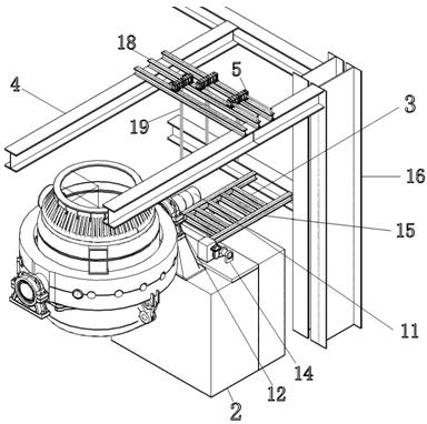
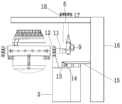
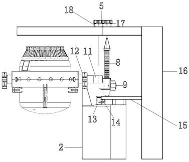
[0015] like Figure 1-7 Shown: a separate installation method for a converter tilting reducer. The specific implementation consists of the following steps:

[0016] Step 1. Disassemble the components of the converter tilting reducer 1

[0017] The converter tilting reducer 1 is decomposed into three parts: the upper box 7, the large ring gear 8, and the lower box 9. The upper box 7 and the lower box 9 are respectively composed of a primary reducer and a secondary reducer. The equipment associated with the installation of the converter tilting reducer 1 includes: the distance ring adjustment device 10, which is set on the converter support ring trunnion 11 to adjust the center distance between the converter tilting reducer 1 and the converter support ring bearing seat 12; A stop seat 13 is provided directly below the bottom of the machine 1; a connecting device is provided at the bottom of the converter tilting reducer 1 and is connected with the torsion bar 14 by connecting b...


PUM


Abstract

The invention relates to a split installation method of a converter tilting speed reducer, and relates to the field of converter steelmaking equipment installation. The method is characterized in that a special supporting platform is erected on the basis of a converter and used for assembling components of the converter tilting speed reducer; a trolley hoisting device is erected on a converter steel structure platform to hoist the components of the converter tilting speed reducer, and the converter tilting speed reducer is adjusted to achieve accurate positioning; and tangential keys are measured, ground, paired and installed by using a freezing method, and finally accessories of the converter tilting speed reducer are installed. According to the method, a split type assembly process is adopted, the construction technical problems that the hoisting weight is large when the converter tilting speed reducer is integrally installed and the converter tilting speed reducer is difficult to install in a limited space of a converter steel structure platform are effectively solved, the installing process of the converter tilting speed reducer is simplified, the construction difficulty is reduced, and the equipment installing precision is improved.

Description

technical field [0001] The invention relates to the technical field of converter steelmaking equipment installation, in particular to a separate installation method for a converter tilting reducer. Background technique [0002] In the installation of the traditional converter tilting reducer, the converter tilting reducer is usually assembled on the converter support ring trunnion before the converter is pushed into place. Each component of the machine weighs 30 tons and the overall weight will exceed 100 tons after being assembled into one body. When using the trolley method to propel the converter, one side of the converter support ring will be biased, and a separate support beam needs to be installed at the bottom of the converter tilting reducer. , the difficulty of synchronous control during the propulsion process of the converter will cause the misalignment of the positioning pin hole of the bearing seat of the converter support ring, which is not conducive to the prec...

Claims


Application Information

Patent Timeline
Patent Type & Authority Applications(China)
IPC IPC(8): B23P21/00C21C5/46C21C5/50
CPCB23P21/00C21C5/46C21C5/50
Inventor 黄轶赵振国阳代茂宋文智崔海洲
Owner SHANGHAI ERSHIYE CONSTR CO LTD
Learn More