Constant-pressure pneumoperitoneum device
A constant pressure, pneumoperitoneum technology, applied in the field of medical devices, can solve the problems of extraction space, inability to keep up with gas volume, unstable pressure, etc.
- Summary
- Abstract
- Description
- Claims
- Application Information
AI Technical Summary
Problems solved by technology
Method used
Image
Examples
Embodiment 1
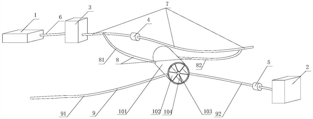
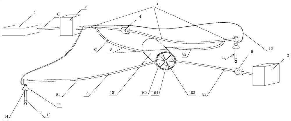
[0031] like figure 1 As shown, a constant pressure insufflation device is provided in this embodiment, including an insufflation machine 1, a suction device 2, a constant pressure container 3 and an intake and exhaust equal volume device 10, and the two ends of the first intake pipe 6 Connect with the exhaust hole of the insufflation machine 1 and the air inlet of the constant pressure container 3 respectively, one end of the second air inlet pipe 7 is connected with the air outlet of the constant pressure container 3, and the two ends of the third air inlet pipe 8 are connected with the second air inlet. Air pipe 7 is connected, and second air inlet pipe 7 is provided with one-way valve 4, and described one-way valve 4 can allow gas to move to the other end from the end that second air inlet pipe 7 is connected with constant pressure container 3, and one-way valve 4 sets Between the two ends of the third intake pipe 8;
[0032] One end of the suction pipe 9 communicates with...
Embodiment 2
[0035] This embodiment is further described on the basis of Embodiment 1. In this embodiment, the air intake and exhaust equalization device 10 includes a sealed box body 101 and a rotating shaft 103, and the sealed box body 101 has a cylindrical cavity , there is a partition in the cavity, and the partition divides the cavity into a front cavity and a rear cavity 102, and the front cavity and the rear cavity 102 are all cylindrical, and the rotating shaft 103 rotates through the partition, and the rotating shaft 103 The two ends of the front chamber are respectively in contact with the front wall of the front chamber and the rear wall of the rear chamber 102. The rotating shaft 103 is provided with a plurality of first blades 104, and the first blades 104 are located in the rear chamber 102. The plurality of first blades 104 are arranged along the The circumferential distribution of the rotating shaft 103, the rear end of the first blade 104 is in contact with the rear wall of...
Embodiment 3
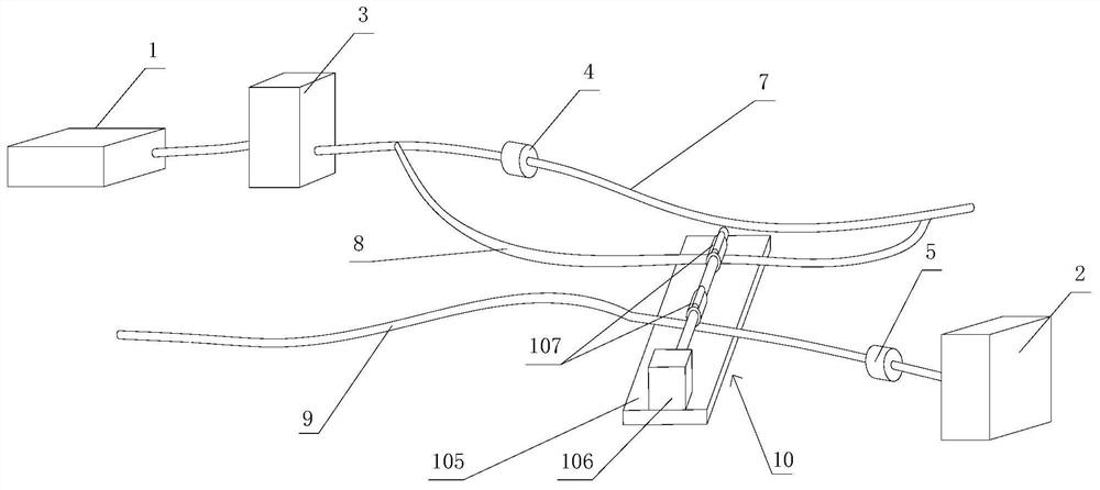
[0041] like figure 2 As shown, this embodiment is further described on the basis of Embodiment 1. In this embodiment, the air intake and exhaust equalization device 10 includes a fixed plate 105, and a driving device 106 is installed on the fixed plate 105. The output shaft of the driving device 106 is connected with two cams 107, the third air intake pipe 8 and the air extraction pipe 9 are placed on the fixed plate 105, and the protruding parts of the two cams 107 can be connected to the third air intake pipe 8 and the air intake pipe 9 respectively. The suction pipe 9 is squeezed and completely closed. When one cam 107 squeezes the third air intake pipe 8, the other cam 107 squeezes the suction pipe 9. One cam 107 can form the abdominal cavity outwards on the suction pipe 9. The negative pressure of exhaust, another cam 107 can form the positive pressure of air intake in the abdominal cavity to the third air intake pipe 8. In this embodiment, the right end of the suction ...
PUM
 Abstract
Description
Claims
Application Information
 - R&D
- Intellectual Property
- Life Sciences
- Materials
- Tech Scout
- Unparalleled Data Quality
- Higher Quality Content
- 60% Fewer Hallucinations
Browse by: Latest US Patents, China's latest patents, Technical Efficacy Thesaurus, Application Domain, Technology Topic, Popular Technical Reports.
© 2025 PatSnap. All rights reserved.Legal|Privacy policy|Modern Slavery Act Transparency Statement|Sitemap|About US| Contact US: help@patsnap.com


