cooking equipment
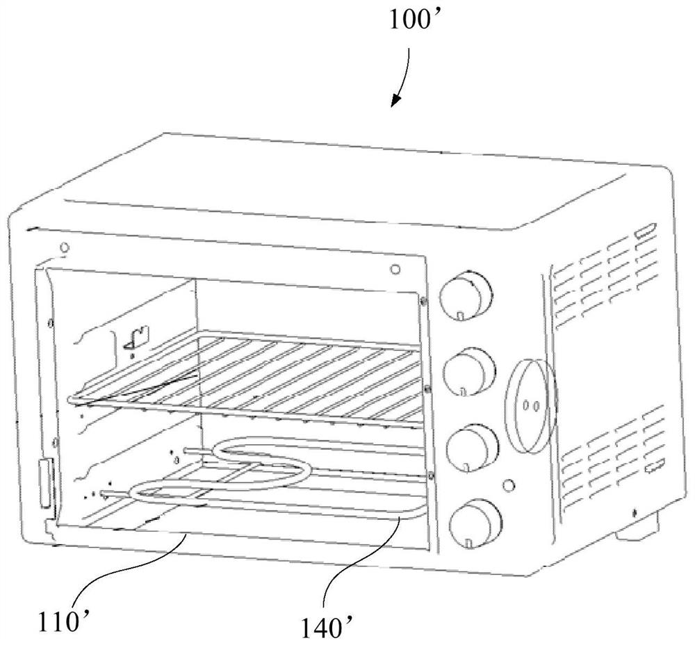
A technology of cooking equipment and a cooking cavity, which is applied in the field of kitchen utensils, can solve problems such as uneven heating of the cooking cavity 110', oil stains, food residues, and affecting the cooking effect of food, so as to improve user experience, high cleanliness, and improve reliability effect
- Summary
- Abstract
- Description
- Claims
- Application Information
AI Technical Summary
Problems solved by technology
Method used
Image


Examples
Embodiment 1
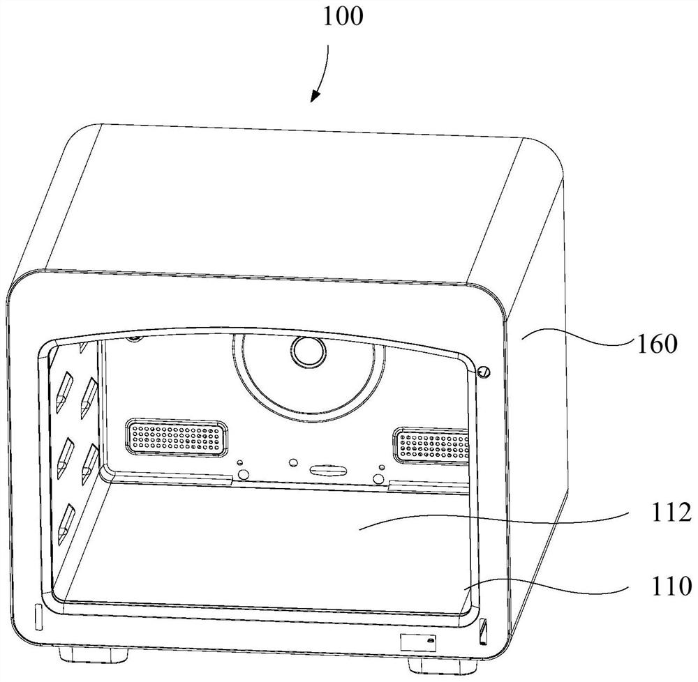
[0063] like Figure 3 to Figure 22 As shown, according to the first aspect of the present invention, a cooking apparatus 100 is provided, which includes a cooking cavity 110, a cover plate 120 and a heat source 140, wherein the cover plate 120 is provided inside or outside the cooking cavity 110, and An accommodating cavity 130 is formed between the cover plate 120 and the cooking cavity 110 ; the heat source 140 is arranged in the accommodating cavity 130 .
[0064] Specifically, as image 3 , Figure 4 , Figure 7 , Figure 8 , Figure 9 As shown, the cover plate 120 of the cooking device 100 is disposed inside or outside the cooking cavity 110, and a accommodating cavity 130 is formed between the cover plate 120 and the cooking cavity 110. By arranging the heat source 140 in the accommodating cavity 130, the heat source can be avoided. 140 is directly arranged in the cooking cavity 110, during the cooking process, there will be oil stains and food 200 residues left on ...
Embodiment 2
[0068] like Figure 3 to Figure 22 As shown, in one embodiment of the present invention, the cooking device 100 includes a cooking cavity 110, a cover plate 120, a heat source 140 and a partition 150, wherein the partition 150 is provided between the heat source 140 and the cooking cavity 110, and Connected to the cover plate 120 .
[0069] In this example, as Figure 4 , Figure 5 , Image 6 , Figure 10 , Figure 11 , Figure 13 , Figure 14 , Figure 15 As shown, a partition 150 is provided between the heat source 140 and the cooking cavity 110, and the partition 150 is opposite to part of the heat source 140. Due to the uneven heat generation of the heat source 140 itself, the partition 150 is connected to the cover plate 120 and to part of the heat source 140. Located opposite to the heat source 140, the partition plate 150 is used to separate the area of the heat source 140 with high calorific value from the cooking cavity 110, which is beneficial to ensure tha...
Embodiment 3
[0073] like Figure 3 to Figure 22 As shown, in one embodiment of the present invention, the cooking apparatus 100 includes a cooking cavity 110, a cover plate 120, a heat source 140 and a partition 150, wherein the cooking cavity 110 is configured as an opening cooking cavity 112, and the cooking cavity 110 includes a plurality of cavity walls 114 , and a cover plate 120 is disposed on at least one of the plurality of cavity walls 114 and is located outside the cooking cavity 112 .
[0074] In this example, as Figure 4 , Figure 5 , Image 6 , Figure 7 , Figure 16 , Figure 17 , Figure 18 , Figure 19 As shown, the cooking cavity 110 is configured as a cooking cavity 112 having an opening, through which the food 200 to be cooked is placed in or taken out from the cooking cavity 110, and the cooking cavity 110 includes a plurality of cavity walls 114, The cover plate 120 is disposed on at least one of the plurality of cavity walls 114, so that the accommodating cav...
PUM
 Abstract
Description
Claims
Application Information
 - Generate Ideas
- Intellectual Property
- Life Sciences
- Materials
- Tech Scout
- Unparalleled Data Quality
- Higher Quality Content
- 60% Fewer Hallucinations
Browse by: Latest US Patents, China's latest patents, Technical Efficacy Thesaurus, Application Domain, Technology Topic, Popular Technical Reports.
© 2025 PatSnap. All rights reserved.Legal|Privacy policy|Modern Slavery Act Transparency Statement|Sitemap|About US| Contact US: help@patsnap.com