
Complex missile-borne cable test system and test method

A cable testing, complex technology, applied in the direction of continuity testing, testing dielectric strength, high resistance measurement, etc., can solve the problems of low efficiency, complexity, and large number of cables in complex cable testing

Inactive Publication Date: 2021-05-04
广州辰创科技发展有限公司
View PDF4 Cites 2 Cited by
  • Summary
  • Abstract
  • Description
  • Claims
  • Application Information

AI Technical Summary

Problems solved by technology

Multi-core cables are often used for the transmission of electric energy and the transmission of control signals within a short distance. With the gradual improvement of the automation level of equipment, in satellites, spacecraft, aircraft, ships, weapons and missiles and other large equipment, the number of cables used is large and complex
To complete the test of a large number of multiple, multi-core, or even hundreds of core cables, such as computer cables, signal cables and control cables, etc., to meet the special requirements of inspection and testing, general cable testers cannot meet the requirements
[0003] At present, the existing cable harness testing technology is mainly oriented to civilian fields such as automotive electronics. It adopts a single chassis-type architecture design, and the type of tested wiring harness is mainly point-to-point testing, which cannot meet the requirements of complex cable network testing and various types of military products used in large quantities. Test requirements for aviation-like connectors and RF connectors
However, the existing means of testing the cables on the fly mainly use multimeters, shakers and other instruments to perform manual tests. The test efficiency for complex cables is extremely low, and the test effect is not good.

Method used


Image

  • Complex missile-borne cable test system and test method
  • Complex missile-borne cable test system and test method

Examples


Embodiment Construction

[0031] Below, the present invention will be further described in conjunction with the accompanying drawings and specific implementation methods. It should be noted that, under the premise of not conflicting, the various embodiments described below or the technical features can be combined arbitrarily to form new embodiments. .

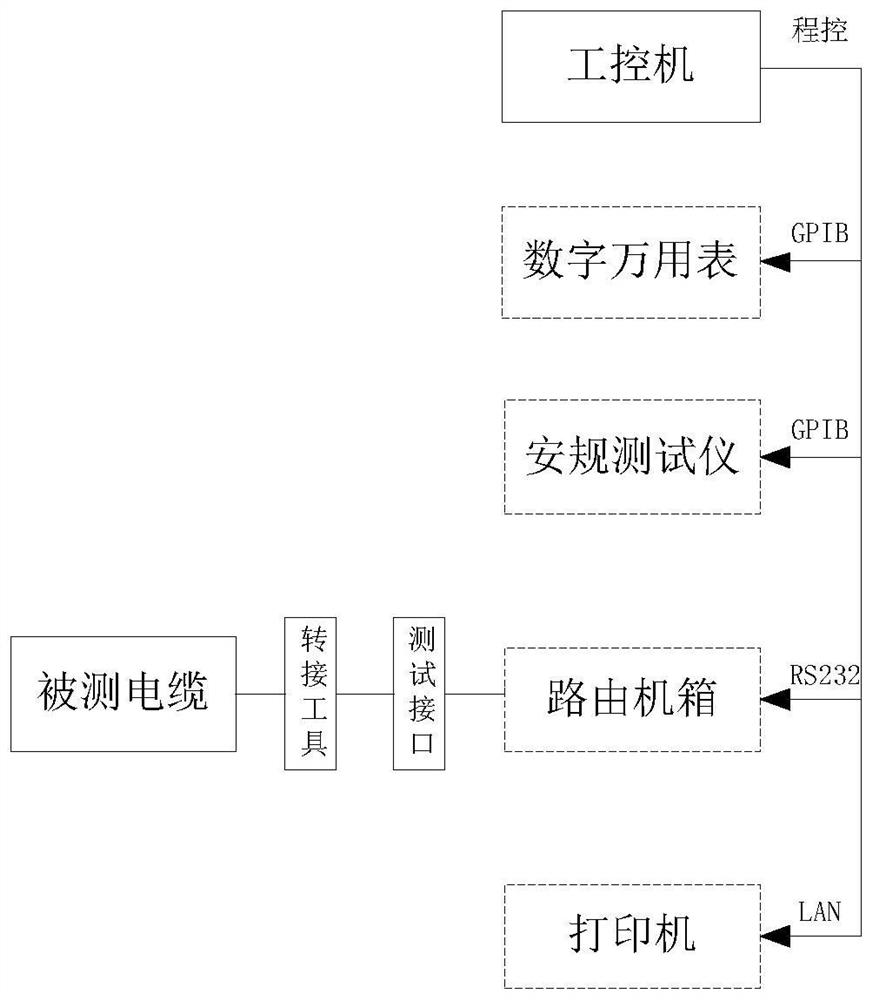
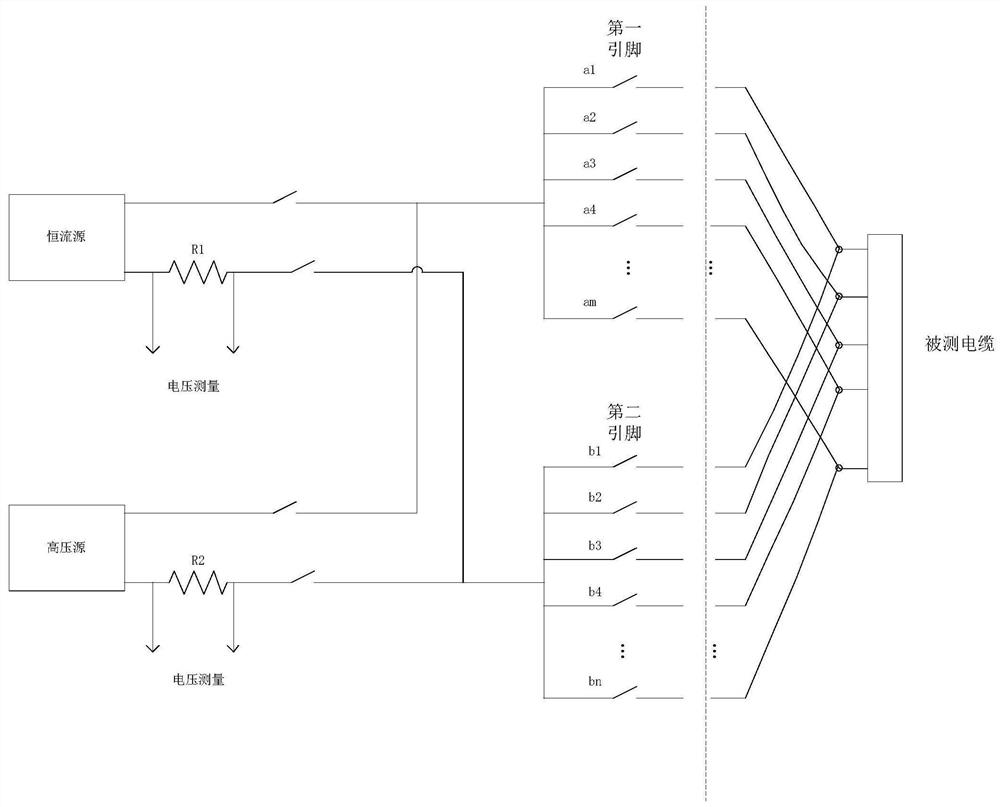
[0032] Such as figure 1 , 2 As shown, the present invention provides a complex spring-on cable testing system, which can be used for factory inspection and acceptance of the spring-on cable, which can be applied to the requirements of production testing, and the test requirement coverage rate is high, realizing multiple test functions and high test efficiency. high.

[0033] Specifically, the complex spring-on cable safety test system includes an industrial computer, a routing chassis and a test module. The industrial computer is the control core of the system. It controls other instruments and equipment through various communication interfaces and ...


PUM


Abstract

The invention discloses a complex missile-borne cable test system and test method, and the system comprises: an industrial personal computer, which is used for inputting a test instruction and receiving and analyzing test data; a routing case, which is connected with the industrial personal computer and is used for receiving a test instruction of the industrial personal computer; wherein the routing case is connected with pins at the two ends of the to-be-tested cable to form a test loop; and a test module, which is connected with the industrial personal computer, receives the test instruction of the industrial personal computer, and tests the conduction, insulation resistance and electrical resistance of the to-be-tested cable. According to the invention, a test instruction can be input through the industrial personal computer, the test module is controlled to test conduction, insulation resistance and electrical resistance of the to-be-tested cable, and the industrial personal computer can directly give a test conclusion according to test data of the test module. The test requirement coverage rate is high, various test functions are achieved, the test efficiency is high, and the method is suitable for production detection.

Description

technical field [0001] The invention relates to the technical field of cable testing, in particular to a complex spring-loaded cable testing system and testing method. Background technique [0002] In the fields of aerospace, national defense and military industry, cables with different performances and sizes are widely used, especially multi-core and multi-head cables. Multi-core cables are often used for the transmission of electric energy and the transmission of control signals within a short distance. With the gradual improvement of the automation level of equipment, in satellites, spacecraft, aircraft, ships, weapons and missiles and other large equipment, the number of cables used is large and complex. To complete the test of a large number of multiple, multi-core, or even hundreds of core cables, such as computer cables, signal cables and control cables, etc., to meet the special requirements of inspection and testing, general cable testers cannot meet the requiremen...

Claims


Application Information

Patent Timeline
IPC IPC(8): G01R31/60G01R31/54G01R27/02G01R27/08G01R31/12
CPCG01R27/025G01R27/08G01R31/1272G01R31/54G01R31/60
Inventor 方卫
Owner 广州辰创科技发展有限公司
Learn More