Microgrid single-end rapid fault positioning method and related device

A fault location and micro-grid technology, applied in the power field, can solve problems such as long time, low positioning accuracy, and unreliability

Active Publication Date: 2021-05-04
ELECTRIC POWER RESEARCH INSTITUTE, CHINA SOUTHERN POWER GRID CO LTD +1
View PDF12 Cites 1 Cited by
  • Summary
  • Abstract
  • Description
  • Claims
  • Application Information

AI Technical Summary

Problems solved by technology

[0005] The embodiment of the present application provides a microgrid single-end rapid fault location method and related devices, which are used to solve the technical problems of low positioning accuracy, long time and unreliability of the existing microgrid fault location technology

Method used


Image

  • Microgrid single-end rapid fault positioning method and related device
  • Microgrid single-end rapid fault positioning method and related device
  • Microgrid single-end rapid fault positioning method and related device

Examples


Embodiment 1

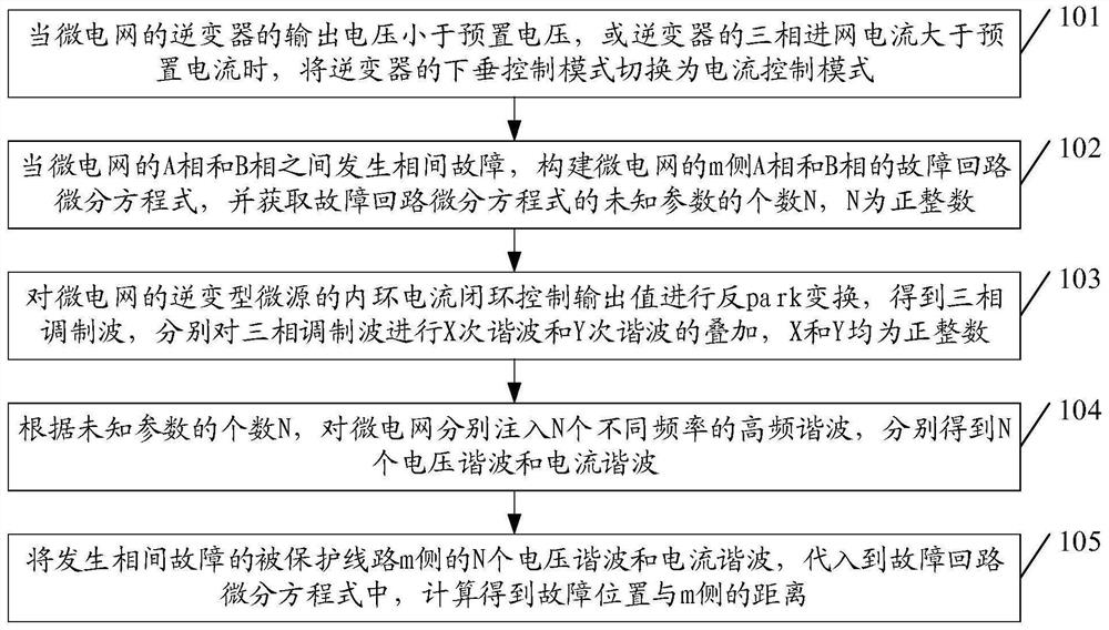
[0048] see figure 1 , Embodiment 1 of a single-end fast fault location method for a microgrid provided in the embodiment of the present application includes:

[0049] Step 101 , when the output voltage of the inverter of the microgrid is lower than the preset voltage, or the three-phase grid current of the inverter is larger than the preset current, switch the droop control mode of the inverter to the current control mode.

[0050] It should be noted that when a fault occurs in the microgrid, the fault detection unit of the microgrid's inverter-type microsource (IBDG) comprehensively judges the changes in the output voltage of the inverter and the phase-incoming grid current, and triggers the corresponding protection setting value (preset voltage and threshold current) to generate a grid fault signal, and then the control system module of the inverter of IBDG switches the droop control mode to the current control mode to realize fault ride-through.

[0051] Step 102. When a p...

Embodiment 2

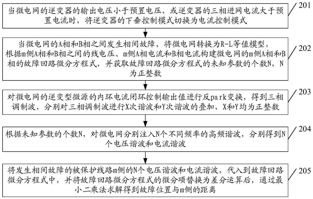
[0061] see figure 2 , Embodiment 2 of a microgrid single-ended fast fault location method provided in the embodiment of the present application includes:

[0062] Step 201 , when the output voltage of the inverter of the microgrid is lower than the preset voltage, or the three-phase grid current of the inverter is larger than the preset current, switch the droop control mode of the inverter to the current control mode.

[0063] Step 201 is the same as the description of step 101 in Embodiment 1, please refer to the description of step 101, and details are not repeated here.

[0064] Step 202, when a phase-to-phase fault occurs between phase A and phase B of the microgrid, convert the microgrid to an R-L equivalent model, according to the line voltage between phase A and phase B on side m, the current of phase A and phase B on side m The current constructs the fault loop differential equations of phase A and phase B of the m-side of the microgrid, and obtains the number N of ...


PUM


Abstract

The invention discloses a microgrid single-end rapid fault positioning method and a related device. Whether a fault occurs or not is judged according to an output voltage or a three-phase grid entering current of a microgrid inverter; when the microgrid breaks down, the droop control mode of the inverter is switched into a current control mode, and fault ride-through is achieved; a fault loop differential equation of a protected line with the fault is construced; then harmonic waves of different times are superposed on a microgrid modulating wave and a plurality of high-frequency harmonic waves of different frequencies are injected into the microgrid so that the microgrid filters the harmonic voltage of the protected line with the fault through the high-frequency harmonic waves to obtain a high-frequency signal; and finally, fault distance calculation is carried out by adopting high-frequency signals in a power grid. According to the invention, rapid, accurate and reliable discrimination and positioning of the microgrid system fault can be completed without communication so that the technical problems of low positioning accuracy, long time and unreliability of the existing microgrid fault positioning technology are solved.

Description

technical field [0001] The present application relates to the field of electric power technology, and in particular to a single-end fast fault location method and related devices of a microgrid. Background technique [0002] As a small power generation and distribution system that organically integrates distributed micro-sources, loads, energy storage devices, and power electronic converters, microgrid can operate in two modes: grid-connected or isolated, and its safe and stable operation capability is to achieve The primary guarantee for the large-scale application of microgrids. However, compared with the characteristics of large grid inertia and strong damping, microgrid, as a power electronic system, presents operating characteristics of small inertia and weak damping. When the system fails, it needs to quickly remove the fault, otherwise it is prone to instability. The system collapses, so the microgrid has high requirements for the rapidity of the relay protection dev...

Claims


Application Information

Patent Timeline
IPC IPC(8): G01R31/08
CPCG01R31/086G01R31/088
Inventor 谈赢杰李晨徐敏袁智勇史训涛徐全胡巨
Owner ELECTRIC POWER RESEARCH INSTITUTE, CHINA SOUTHERN POWER GRID CO LTD
Why Eureka
Try Eureka