
Spinning frame and joint operation method thereof

An operation method and spinning frame technology, applied to spinning machines, jointing devices, textiles and papermaking, etc., can solve problems such as waste of electric energy and roving, and achieve the effects of avoiding equipment failure, reducing production costs, and eliminating flying flowers

Active Publication Date: 2021-05-04
SAURER (JIANGSU) TEXTILE MASCH CO LTD
View PDF7 Cites 1 Cited by
  • Summary
  • Abstract
  • Description
  • Claims
  • Application Information

AI Technical Summary

Problems solved by technology

When the yarn breaks, the suction pipe sucks the broken ends or cotton fibers or flying flowers into the main air duct of the spinning frame through the suction pipe. Usually, the suction pipe fan needs to be started 24 hours a day without interruption. However, the suction The trachea will only work to inhale cotton fibers when the yarn breaks, and the unnecessary work of the suction pipe fan for a long time will inevitably cause a lot of waste of electric energy and roving

Method used


Image

  • Spinning frame and joint operation method thereof
  • Spinning frame and joint operation method thereof
  • Spinning frame and joint operation method thereof

Examples


Embodiment 1

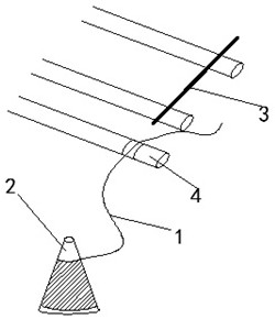
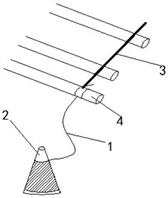
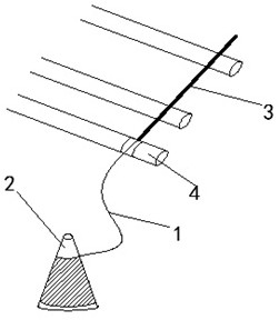
[0033] This embodiment describes a splicing operation method of a spinning frame, the spinning frame includes several rows of stations arranged side by side, each station includes a drafting mechanism for drafting the roving 3 into fiber bundles, a rotatable Spindle 2 for forming bobbins, a broken yarn detection device, the drafting mechanism includes a plurality of roller pairs including the bottom roller 4, and the splicing operation of each station can be performed without a negative pressure yarn suction device. carry out and include steps such as Figure 4 Shown:

[0034] A: Roving stop steps:

[0035] The broken yarn detection device keeps the detection of the state of the yarn 1, and when it detects that a certain station in the spinning frame has a broken yarn, the spinning frame immediately stops the roving 3 feeding roller of the station, Thereby stopping the feeding of the roving 3;

[0036] B: Yarn placement steps:

[0037] Such as figure 1 As shown, the yarn ...

Embodiment 2

[0046] This embodiment also provides a spinning frame for implementing the joint operation method described in Embodiment 1, each station of the spinning frame further includes a roving self-stopping device, and the roving self-stopping device is used to perform the step The roving stop step in A, that is, when the broken yarn detection device detects that the broken yarn occurs, the roving self-stopping device automatically stops the feeding of the roving at the station, which can effectively prevent the generation of flying flowers and avoid causing machine failure or yarn breakage. Line quality problem.

[0047] In this embodiment, each spindle 2 of the fine spinning machine is controlled by a separate motor, and when a yarn breakage occurs, the motor of the spindle 2 at the yarn breakage position controls the spindle 2 to automatically stop running. When the spinning machine station executes the yarn placement step B of the above method, after the spindle 2 stops running a...


PUM


Abstract

The invention relates to a spinning frame and a joint operation method thereof. The spinning frame comprises a plurality of rows of stations; each station comprises a drafting mechanism, a spindle used for forming a spool and a broken yarn detection device; the drafting mechanism comprises a plurality of roller pairs including a lower roller; joint operation of each station is carried out under a non-negative-pressure yarn suction device and comprises the following steps that when yarn breakage of the spinning frame is detected, a rough yarn feeding roller of the station is stopped, and rough yarn feeding is stopped; the yarn with the set length is placed on one roller, and the length from the contact point of the yarn and the roller to the tail end of the yarn is the set length; and rough yarn feeding and spindle rotation are started, so that the rough yarn and the yarn tail end move at the same time and meet in the joint area, and joints are formed under the condition that the rough yarn is not wasted. According to the spinning frame, the rough yarn splicing action in the state without an air suction pipe can be achieved, splicing is accurate, the phenomenon of yarn flying is avoided, the production cost of the spinning frame can be saved, and meanwhile equipment failures or yarn quality problems are avoided.

Description

technical field [0001] The invention relates to the technical field of textile machinery, in particular to a splicing operation method of a spinning frame and the spinning frame. Background technique [0002] Spinning frame is a spinning machine that draws, twists, and winds semi-finished roving or sliver into spun bobbin during the spinning process. The sliver is drafted and twisted on the roving frame to make roving, the comber combs the fiber to make a combed sliver, the needle card machine combines the sliver, the needle row drafting improves the sliver structure, and the roving is further twisted and spun on the ring spinning frame into spun yarn, and the spinning frame is the main machine for spinning. [0003] During the spinning process of the spinning frame, whether it is a normal spinning splicing or a broken thread, it needs to be spliced ​​at the spinning frame. During the splicing, the roving is passed through the drafting device and is continuously carried out...

Claims


Application Information

Patent Timeline
Patent Type & Authority Applications(China)
IPC IPC(8): D01H15/00D01H13/16
CPCD01H15/00D01H13/16Y02W30/66
Inventor 柯斯特纳·亚历山大
Owner SAURER (JIANGSU) TEXTILE MASCH CO LTD
Learn More