Eureka AIR delivers breakthrough ideas for toughest innovation challenges, trusted by R&D personnel around the world.

Anti-winding and rolling integrated ribbon loom

An anti-winding and integrated technology, which is applied in the direction of winding strips, textiles and papermaking, and textile material cutting, etc. It can solve the problems of ribbon folding, intertwining of ribbons, and increasing the occupied area of ​​the ribbon loom.

Pending Publication Date: 2021-05-04
义乌亮彩织带有限公司
View PDF0 Cites 2 Cited by
  • Summary
  • Abstract
  • Description
  • Claims
  • Application Information

AI Technical Summary

Problems solved by technology

[0003] In the prior art, the thread roll to be woven is installed on one end of the ribbon loom, and the textile thread to be woven is woven through the warping device and the weaving device in turn, and then the woven ribbon is gradually extended from the other end of the ribbon loom. The machine needs to wind the tape after the weaving is completed. However, most of the existing winding methods are manually wound after the processing is completed or the webbing is extended to the next station to be wound by the machine, which is easy to cause the webbing to turn over, not Flat, even the ribbons are entangled with each other, which makes the winding work inefficient. At the same time, the transition of the ribbon to the next station not only increases the occupied area of ​​the ribbon loom, but also tends to cause artificial accidental contamination of the ribbon

Method used


Image

  • Anti-winding and rolling integrated ribbon loom
  • Anti-winding and rolling integrated ribbon loom
  • Anti-winding and rolling integrated ribbon loom

Examples


Embodiment 1

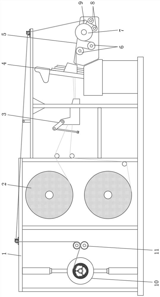
[0033] Embodiment one, with reference to Figure 1-2 , an anti-winding and winding integrated ribbon loom, comprising a frame 1, a warping device 3, a weaving device 4, an anti-winding mechanism 5, a winding mechanism 10 and a cutting mechanism 11, and the inside of the frame 1 is provided with a winding mechanism from right to left. Roll mechanism 10, cutting mechanism 11, wire reel 2, warping device 3, textile device 4, anti-winding mechanism 5, wire reel 2 is provided with two altogether from top to bottom, and the yarn of two wire reels 2 is equal Pass through warping device 3 and weaving device 4 in sequence and weave and form the webbing into anti-winding mechanism 5. Anti-winding mechanism 5 includes first flattening roller 6, driving roller 7, second flattening roller 8, third flattening roller 9. The mounting frame 12, the first paving roller 6, the driving roller 7, the second paving roller 8, and the third paving roller 9 are all erected and fixed by the mounting fr...

Embodiment 2

[0035] Embodiment two, refer to figure 1 and image 3 , the top of the frame 1 is provided with a plurality of transition rollers for erecting the webbing from left to right, and the anti-winding mechanism 5, the cutting mechanism 11 and the winding mechanism 10 are connected by the webbing, and the winding mechanism 10 includes a winding drum 13, a rotating shaft 14. The bearing housing 15, the winding motor 16, the winding motor 16 is installed on one side surface of the frame 1 through the fixing plate, and the output shaft of the winding motor 16 is rotationally connected with one end of the rotating shaft 14 fixed by the bearing housing 15;

[0036]The ribbon weaved by the ribbon loom enters the winding mechanism 10 from the anti-winding mechanism 5 through the top of the frame 1. The rational use of space and the integrated structure design make the ribbon loom compact in structure, which not only reduces the occupied area of ​​the ribbon loom, but also avoids The pheno...

Embodiment 3

[0037] Embodiment three, refer to Figure 3-5 A lower electric telescopic rod 18 and a lower connecting block 20 are arranged below the other end of the rotating shaft 14, and the lower connecting block 20 is fixed on the upper end surface of the lower electric telescopic rod 18, and a buffer pad 22 and an upper connecting block 19 are successively arranged above the lower connecting block 20. 1. The upper electric telescopic rod 17 is fixedly connected, and one side of the lower connecting block 20 and the upper connecting block 19 are equipped with rollers 21 through pin shafts, and three rollers 21 are arranged in a triangular distribution, and the surface of the rotating shaft 14 is covered with a guide sleeve 23, and the guide sleeve 23 is slidably connected with the rotating shaft 14 to open the limit groove 28, the guide sleeve 23 below is hinged with the support plate 25 through the connecting rod 24, and the surface on one side of the guide sleeve 23 is fixedly connect...


PUM


Abstract

The invention discloses an anti-winding and rolling integrated ribbon loom which comprises a frame, a warping device, a spinning device, an anti-winding mechanism, a rolling mechanism and a cutting mechanism. The rolling mechanism, the cutting mechanism, a thread coil, the warping device, the spinning device and the anti-winding mechanism are sequentially arranged in the frame from right to left. According to the anti-winding and rolling integrated ribbon loom, a braid woven and formed through the spinning device enters the anti-winding mechanism and is sequentially wound around a first tiling roller, a driving roller, a second tiling roller and a third tiling roller, the surface of the driving roller is wrapped with roller leather, the friction force of the driving roller to the braid can be increased, and meanwhile under the action of the first tiling roller and the second tiling roller, the contact area between the braid and the surface of the driving roller is reasonably increased, the slipping phenomenon between the driving roller and the braid is avoided, under the action of the driving roller, the braid can be flattened and combed through the first tiling roller, and the braid is prevented from being folded and wound.

Description

technical field [0001] The invention relates to the technical field of ribbon processing equipment, in particular to an anti-winding and winding integrated ribbon loom. Background technique [0002] Ribbon looms, machines that can weave ribbons of various widths are ribbon looms. Ribbon is made of various yarns as narrow fabrics or tubular fabrics. [0003] In the prior art, the thread roll to be woven is installed on one end of the ribbon loom, and the textile thread to be woven is woven through the warping device and the weaving device in turn, and then the woven ribbon is gradually extended from the other end of the ribbon loom. The machine needs to wind the tape after the weaving is completed. However, most of the existing winding methods are manually wound after the processing is completed or the webbing is extended to the next station to be wound by the machine, which is easy to cause the webbing to turn over, not Flat, even the ribbons are entangled with each other,...

Claims


Application Information

Patent Timeline
IPC IPC(8): B65H18/10B65H18/04B65H18/02B65H75/24B65H23/26B65H19/26B65H27/00D06H7/02
CPCB65H18/02B65H18/04B65H18/106B65H19/265B65H23/26B65H27/00B65H75/242B65H2701/174D06H7/02
Inventor 骆洋军王起任大龙
Owner 义乌亮彩织带有限公司
Why Eureka
Eureka Blog
Learn More