
Emergency life raft with wave current power generation function

A technology of life rafts and DC generators, applied in life rafts, hydroelectric power generation, ocean energy power generation, etc., can solve the problems of battery exhaustion, long floating time, and threats to the safety of escapees, so as to improve confidence and survival courage Effect

Pending Publication Date: 2021-05-04
中石化石油工程技术服务有限公司 +2
View PDF0 Cites 0 Cited by
  • Summary
  • Abstract
  • Description
  • Claims
  • Application Information

AI Technical Summary

Problems solved by technology

[0004] However, due to the limited capacity of the existing life rafts equipped with batteries, the floating time at sea is too long, and the power of the batteries is exhausted, which will cause a very serious threat to the safety of escapees. Therefore, there is an urgent need for a marine emergency life raft with self-generating function.

Method used


Image

  • Emergency life raft with wave current power generation function
  • Emergency life raft with wave current power generation function

Examples


Embodiment 1

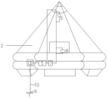
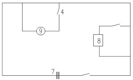
[0021] An emergency life raft with wave current power generation, comprising a life raft 2, a battery 7 arranged on the life raft 2, a switch circuit 4 connected to the battery 7, a lighting lamp 9, a communication device 8, and a battery 7 arranged on the life raft 2 The DC generator 5 is connected to the wave current action blade 1 drivingly connected to the DC generator 5, and the electric output of the DC generator 5 is connected to the storage battery 7.

Embodiment 2

[0023] On the basis of embodiment 1, further comprising:

[0024] The direct current generator 5 is connected and driven with the wave flow action blade 1 through a connecting rod 10 .

[0025] A flexible soft connecting rod 6 is connected between the wave flow action blade 1 and the connecting rod 10 .

[0026] The DC generator 5 establishes a driving connection with the wave flow action blade 1 through the reduction gear box 3 .

[0027] A charging protector is also connected between the DC generator 5 and the storage battery 7 .

[0028] The DC generator 5 and the reduction gearbox 3 are arranged at the bottom of the liferaft 2 .

Embodiment 3

[0030] An emergency life raft with wave current power generation, including life raft 2, wave current action blade 1, connecting rod 10, reduction gear box 3, switch circuit 4, small DC generator 5, small battery 7, lighting lamp 9, communication Equipment 8 etc.

[0031] The device rotates under the action of the wave and current force through the underwater impeller to drive a small DC generator to generate an induced current, so that the lighting and communication devices that are crucial to escape at sea can continue to work. The device can be fixed in the life raft box at ordinary times, and the fixed position makes the device be in a more suitable operating position after the life raft is launched. Or adjust the liferaft after it has been launched. It can also be temporarily fixed. If such devices are installed on offshore ships and offshore platforms, personnel on board should be trained in operation to ensure safe and effective use of the device in emergency situatio...


PUM


Abstract

The invention provides an emergency life raft with a wave current power generation function. The emergency life raft comprises a life raft, a storage battery arranged on the life raft, a switching circuit connected with the storage battery, an illuminating lamp, a communication device, a direct-current generator arranged on the life raft, and a wave current acting blade in driving connection with the direct-current generator, and the electric output of the direct-current generator is connected with the storage battery. The emergency life raft with the wave current power generation function has the advantages that a circuit system of the life raft is charged on the sea through the wave current force, illumination and communication functions of the life raft are achieved, power comes from natural wave current, and energy conservation and environmental protection are achieved. The rescue of the marine life raft is greatly helped, and meanwhile, the confidence and survival brave of personnel on the life raft are greatly improved.

Description

technical field [0001] The invention relates to a marine emergency life-saving raft and belongs to the field of marine life-saving devices. [0002] technical background [0003] The escape of a ship or offshore platform in an accident at sea is related to the safety of life and has always been widely concerned. Life raft is a common equipment for escape at sea. Compared with life boats, life rafts are simple to operate, and the escape position is not restricted, which is convenient and flexible. However, life rafts have no self-propulsion capability. The radio station is very necessary. The signal lights enable ships passing by at sea to see and come to rescue them. The life-saving radio station can send out a distress signal to get rescue from afar. [0004] However, due to the limited battery capacity of the existing life rafts, the floating time at sea is too long, and the power of the batteries is exhausted, which will cause a very serious threat to the safety of escape...

Claims


Application Information

Patent Timeline
Patent Type & Authority Applications(China)
IPC IPC(8): B63C9/04F03B13/14F03B13/10
CPCB63B2209/14B63C9/04F03B13/10F03B13/14Y02E10/20Y02E10/30
Inventor 柏健张爱恩崔希君邬可谊魏羲崔青张红胜
Owner 中石化石油工程技术服务有限公司
Learn More