
A feeder used in a placement machine

A feeder and placement machine technology, applied in the direction of electrical components, electrical components, etc., can solve the problems of poor protection performance, material tape stuck inside the equipment, poor flexibility of use of the feeder, etc., to improve the protection performance , Increase the range of use, reduce the effect of offset

Active Publication Date: 2022-03-01
RAYVAL SUZHOU TECH
View PDF10 Cites 0 Cited by
  • Summary
  • Abstract
  • Description
  • Claims
  • Application Information

AI Technical Summary

Problems solved by technology

[0003] Aiming at the deficiencies of the prior art, the present invention provides a feeder used in the placement machine, which solves the problem that the existing feeder of the placement machine proposed in the above-mentioned background technology has poor flexibility in use, and during use It is impossible to transport and separate electronic chips for various types of tapes, and the protection performance is poor. When separating electronic chips, it is easy to scratch the electronic chips, and it is easy to cause the tape to be stuck inside the equipment, causing the feeder to fail to operate normally. The problem

Method used


Image

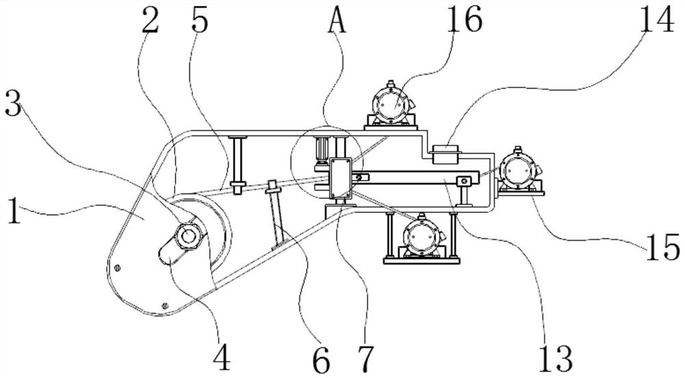
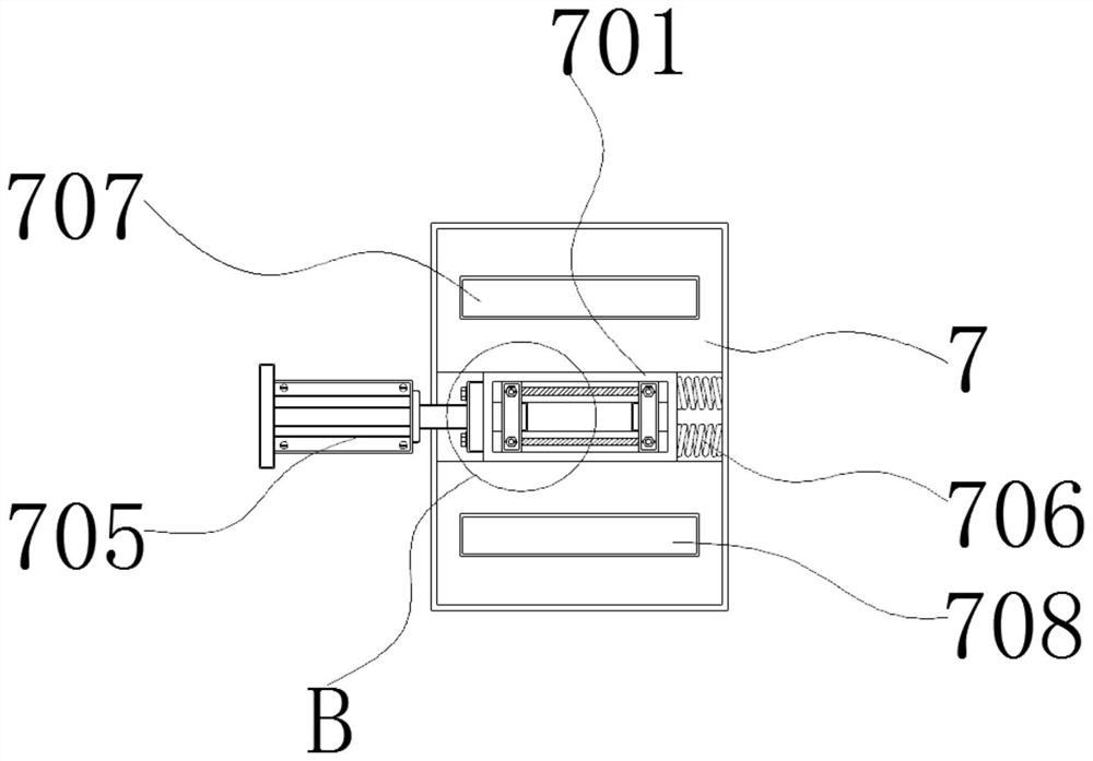
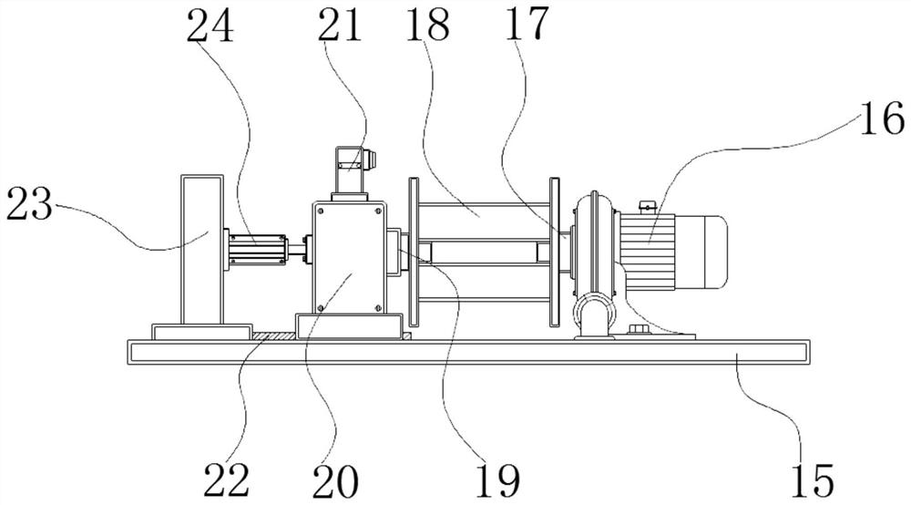
  • A feeder used in a placement machine
  • A feeder used in a placement machine
  • A feeder used in a placement machine

Examples


Embodiment Construction

[0027] The following will clearly and completely describe the technical solutions in the embodiments of the present invention with reference to the accompanying drawings in the embodiments of the present invention. Obviously, the described embodiments are only some, not all, embodiments of the present invention.

[0028] In the description of the present invention, unless otherwise stated, the meaning of "plurality" is two or more; the terms "upper", "lower", "left", "right", "inner", "outer" , "front end", "rear end", "head", "tail", etc. indicate the orientation or positional relationship based on the orientation or positional relationship shown in the drawings, and are only for the convenience of describing the present invention and simplifying the description, rather than Nothing indicating or implying that a referenced device or element must have a particular orientation, be constructed, and operate in a particular orientation should therefore not be construed as limiting ...


PUM


Abstract

The invention discloses a feeder used in a chip mounter, relates to the technical field of chip mounters, in particular to a feeder used in a chip mounter. The feeder used in the placement machine, the feeder includes a feeder housing and a blocking structure, the blocking structure is arranged at the middle end of the inner side of the feeding housing, and the inner side of the feeding housing is provided with a set A material seat, and the outside of the material seat is connected with a clamping seat on both sides, the outside of the clamping seat is provided with a sliding groove, and the outside of the material seat is connected with a material belt. The feeder used in the placement machine, the rotation of the motor can transmit the material belt, because the material belt in the front section is separated into three parts, which makes the material belt that moves later and is close to the block structure can be separated naturally , which allows the equipment to naturally separate the tape without using a separation device, which can effectively avoid scratches on the electronic chip caused by the use of the separation device, which is conducive to improving the protection performance of the equipment.

Description

technical field [0001] The invention relates to the technical field of placement machines, in particular to a feeder used in placement machines. Background technique [0002] Mounter, also known as placement machine, is a device that accurately places surface mount components on PCB pads by moving the placement head after the placement machine is configured on the dispensing machine or screen printing machine in the production line. The feeder of the chip machine can transport the material tape with the electronic chip and separate the material tape from the electronic chip. This type of material tape is used for transmission and separation of electronic chips, and the protection performance is poor. When separating electronic chips, it is easy to scratch the electronic chip, and it is easy to cause the material tape to be stuck inside the equipment, causing the feeder to fail to operate normally. Contents of the invention [0003] Aiming at the deficiencies of the prior ...

Claims


Application Information

Patent Timeline
Patent Type & Authority Patents(China)
IPC IPC(8): H05K13/04H05K13/08
CPCH05K13/04H05K13/0417H05K13/0404H05K13/0812
Inventor 王胜亮
Owner RAYVAL SUZHOU TECH
Learn More