Photovoltaic module

A photovoltaic module and photovoltaic cell technology, applied in the field of solar photovoltaic power generation, can solve the problems of limited UV resistance and poor weather resistance, and achieve the effects of good UV resistance, good UV resistance and good flexibility

Pending Publication Date: 2021-04-30
INST OF ADVANCED TECH UNIV OF SCI & TECH OF CHINA
View PDF0 Cites 0 Cited by
  • Summary
  • Abstract
  • Description
  • Claims
  • Application Information

AI Technical Summary

Problems solved by technology

The low-cost solar backsheet solution is to use an anti-ultraviolet agent, coated and modified PET polyester film to replace fluorine-containing materials, but the PET material modified by anti-ultraviolet coating not only has limited anti-ultraviolet ability, but also has poor weather resistance. , and its manufacturing process is a non-environmentally friendly chemical coating process

Method used


Image

  • Photovoltaic module
  • Photovoltaic module
  • Photovoltaic module

Examples


Embodiment 1

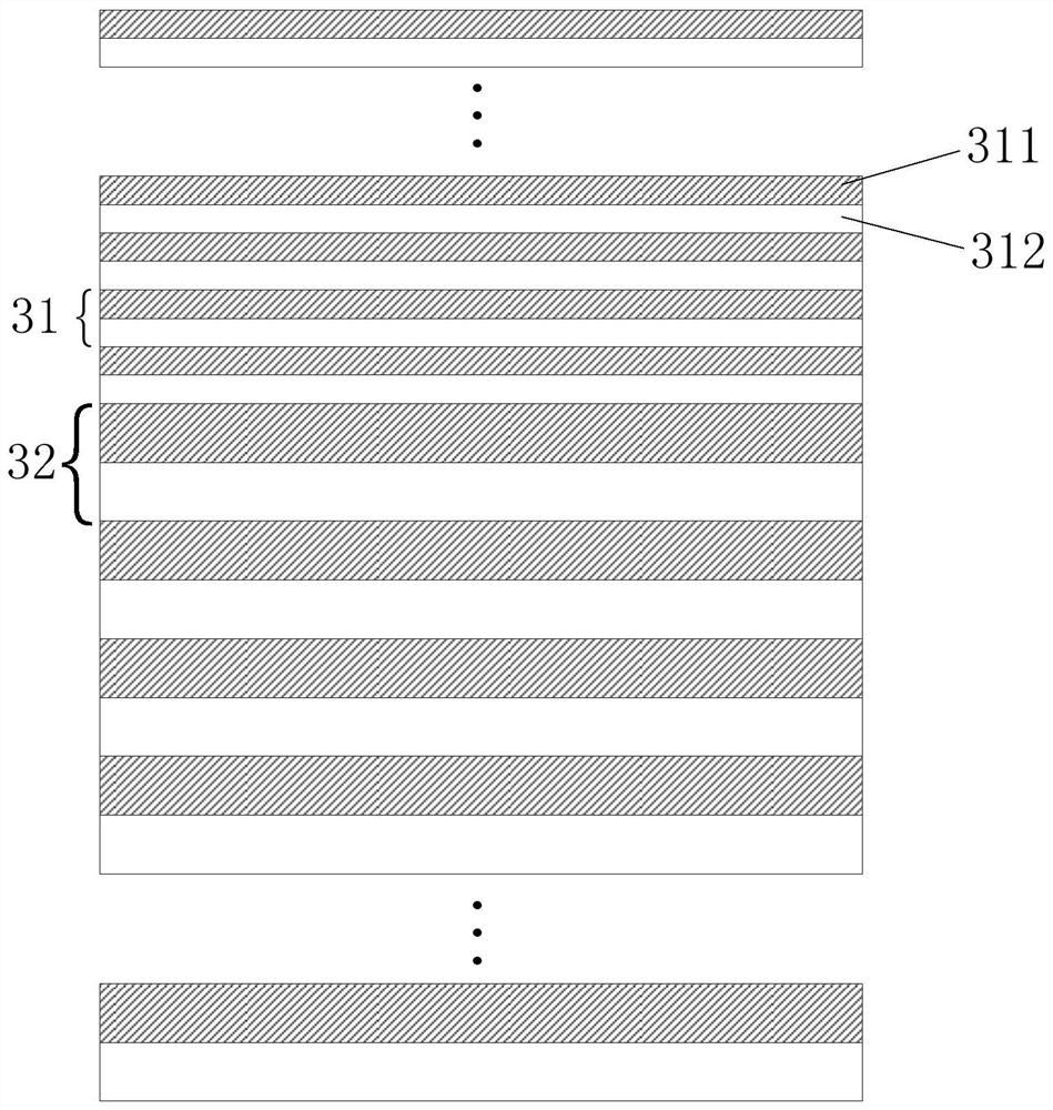
[0075]Taking PMMA and PC materials to design the first combined film structure with excellent UV resistance as an example, in order to obtain a wider emission bandwidth at a wavelength of 365nm, the first reflective film group 31 is designed for selective high reflection wavelength λ 1 For ultraviolet rays of 365nm, the second reflection film group 32 is used for selective high reflection wavelength λ 2 UV rays of 354nm. According to n × d=λ / 4, in the first reflective film group 31, the thickness of the PMMA layer is 61.2nm, and the thickness of the PC layer is 57.6nm; in the second reflective film group 32, the thickness of the PMMA layer is 59.4nm, The thickness of the PC layer was 55.8 nm.

[0076] In actual operation, set the set temperature range of the extruder to 280°C, 275°C, 270°C, 265°C, 260°C, set the temperature of the multiplier and the extrusion die to 260°C and 220°C respectively, and cast the cooling roll The set temperature is 120°C. Firstly, 128 sets of re...

Embodiment 2

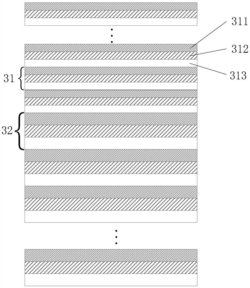
[0079] Taking PMMA and PC materials to design the first combined film structure with excellent UV resistance as an example, the first reflective film group 31 is designed for selective high reflection wavelength λ 1 For ultraviolet rays of 365nm, the second reflection film group 32 is used for selective high reflection wavelength λ 2 UV rays of 1100nm. According to n × d=λ / 4, in the first reflective film group 31, the thickness of the PMMA layer is 61.2nm, and the thickness of the PC layer is 57.6nm; in the second reflective film group 32, the thickness of the PMMA layer is 184.6nm, The thickness of the PC layer was 173.5 nm.

[0080] In actual operation, set the set temperature range of the extruder to 280°C, 275°C, 270°C, 265°C, 260°C, set the temperature of the multiplier and the extrusion die to 260°C and 220°C respectively, and cast the cooling roll The set temperature is 120°C. Firstly, 128 groups of reflective film groups with equal thickness are obtained by stacking...


PUM

PropertyMeasurementUnit
Thicknessaaaaaaaaaa
Thicknessaaaaaaaaaa
Thicknessaaaaaaaaaa

Abstract

The invention provides a photovoltaic module which comprises a photovoltaic cell and a first combined film structure, wherein the first combined film structure is located on the back surface of the photovoltaic cell, the first combined film structure comprises a plurality of transparent film layers, and at least two first reflection interfaces are formed on the plurality of transparent film layers; the ultraviolet light is reflected from the two first reflection interfaces to form the first reflection light and the second reflection light which deviate from the photovoltaic cell, and the first reflection light and the second reflection light can interfere with each other in a constructive manner, so that the reflection of the ultraviolet light is selectively improved. The first combined film structure provided by the invention is good in ultraviolet resistance and low in cost. Therefore, the photovoltaic module using the first combined film structure is good in ultraviolet resistance, low in cost, good in flexibility and wide in application range, and can be applied to automobiles, ships, color steel tile roofs, building curtain walls and the like.

Description

technical field [0001] The invention relates to the field of solar photovoltaic power generation, in particular to a photovoltaic module. Background technique [0002] The solar backsheet is an important part of the solar photovoltaic cell structure, which plays an insulating and protective role for the solar photovoltaic cells. The mainstream solar backsheet in the world is a composite backsheet material made of fluorine-containing materials. Most of the backplanes used by domestic component manufacturers rely on imports, the market price is relatively high, and the technology is monopolized by foreign companies. The low-cost solar backsheet solution is to use an anti-ultraviolet agent, coated and modified PET polyester film to replace fluorine-containing materials, but the PET material modified by anti-ultraviolet coating not only has limited anti-ultraviolet ability, but also has poor weather resistance. , and its manufacturing process is a non-environmentally friendly ...

Claims


Application Information

Patent Timeline
IPC IPC(8): H01L31/056H01L31/049
CPCH01L31/049H01L31/056Y02B10/10Y02E10/52
Inventor 李明张放心张昕昱刘文
Owner INST OF ADVANCED TECH UNIV OF SCI & TECH OF CHINA
Why Eureka
Try Eureka