
Pantograph carbon contact strip abrasion detection system

A pantograph carbon slide and detection system technology, applied in the direction of instruments, calculations, computer components, etc., can solve the problems of inability to realize online monitoring, high cost, and great influence on measurement accuracy, and achieve simple, efficient, and accurate measurement methods high effect

Active Publication Date: 2021-04-30
攀枝花容则钒钛有限公司
View PDF9 Cites 3 Cited by
  • Summary
  • Abstract
  • Description
  • Claims
  • Application Information

AI Technical Summary

Problems solved by technology

From the perspective of its development history, the pantograph slide wear detection has gradually developed from the initial manual measurement on the vehicle to the measurement method of the optical fiber wear sensor, and then to the current image online measurement. The measurement method is becoming more and more convenient and efficient. It is also getting higher and higher, but these three methods have their inherent disadvantages: the manual work is heavy, and online monitoring cannot be realized; the fiber optic wear sensor needs to install a set of equipment at each slide, which is very costly; intelligent Online measurement is mainly ultrasonic measurement, laser measurement and image measurement, but intelligent online measurement is greatly affected by weather conditions. The device is installed on a fixed elevated frame, the cost is high, and the measurement accuracy is greatly affected by the state of the pantograph and the trigger position, so it is difficult to achieve high measurement accuracy

Method used


Image

  • Pantograph carbon contact strip abrasion detection system
  • Pantograph carbon contact strip abrasion detection system

Examples


Embodiment 1

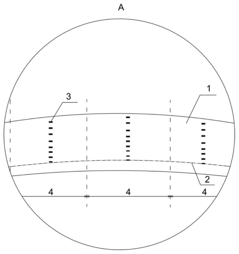
[0035] A pantograph carbon sliding plate wear detection system, including a data acquisition unit, a data processing unit and a control center, the data acquisition unit includes a radio frequency tag and a radio frequency reader, the control center controls the work of the radio frequency reader, and the control center is in After each lowering of the bow, when the temperature of the pantograph drops to room temperature, the read information is sent to the RF reader;

[0036] The radio frequency tags are arranged in different areas and at different depths of the wear area of ​​the carbon slide plate of the pantograph. When wear occurs, the radio frequency tags in the corresponding wear area will be damaged or dropped;

[0037] The radio frequency reader is installed on the roof of the train. When the radio frequency reader receives the reading information sent by the control center, it sends an inquiry signal to the radio frequency tag and reads the undamaged radio frequency r...

Embodiment 2

[0043] A pantograph carbon sliding plate wear detection system, including a data acquisition unit, a data processing unit and a control center, the data acquisition unit includes a radio frequency tag and a radio frequency reader, the control center controls the work of the radio frequency reader, and the control center is in After each lowering of the bow, when the temperature of the pantograph drops to room temperature, the read information is sent to the RF reader;

[0044] The radio frequency tags are arranged in different areas and at different depths of the wear area of ​​the carbon slide plate of the pantograph. When wear occurs, the radio frequency tags in the corresponding wear area will be damaged or dropped;

[0045] The radio frequency reader is installed on the roof of the train. When the radio frequency reader receives the reading information sent by the control center, it sends an inquiry signal to the radio frequency tag and reads the undamaged radio frequency r...


PUM


Abstract

A pantograph carbon contact strip abrasion detection system comprises a data acquisition unit, a data processing unit and a control center, the data acquisition unit comprises radio frequency tags and a radio frequency reader-writer, and the control center controls the radio frequency reader-writer to work; the radio frequency tags are distributed in different areas and different depths of a pantograph carbon contact strip abrasion area; the radio frequency reader-writer reads an undamaged radio frequency tag left on the pantograph carbon contact strip, receives the inquiry signal, returns a response signal containing identity information, and sends the response signal to the data processing unit; the data processing unit stores the identity information of all the radio frequency tags and the arrangement position of each radio frequency tag on the pantograph carbon contact strip, according to the identity information read by the radio frequency reader-writer, the damage and falling conditions of the radio frequency tags in different abrasion areas are counted and analyzed, and then the abrasion value and the abrasion area of the pantograph carbon contact strip are judged. The detection system is high in detection efficiency, high in precision and low in cost.

Description

technical field [0001] The invention relates to the technical field of pantograph carbon sliding plate detection, in particular to a pantograph carbon sliding plate wear detection system based on RFID technology. Background technique [0002] With the rapid development of my country's high-speed railway in recent years and the development of railway freight in the direction of heavy load, the railway department pays more and more attention to the safety of train driving. As an important part of the train power supply drive system, the pantograph is directly connected to the catenary, and obtains current from the catenary to drive the train to run normally. If the pantograph-catenary system breaks down, the train will lose its power, which will easily cause serious railway traffic accidents and cause great economic losses. Therefore, it is of great significance to carry out dynamic detection on the pantograph-catenary system of trains and grasp the operating state of the pan...

Claims


Application Information

Patent Timeline
Patent Type & Authority Applications(China)
IPC IPC(8): G06K17/00
CPCG06K17/0029
Inventor 苟国庆文蓉
Owner 攀枝花容则钒钛有限公司
Learn More