Object-carrying glassware, fluorescence microscopic imaging device and use method
A technology of object-carrying glass and microscopic imaging, which is applied in the direction of measuring devices, fluorescence/phosphorescence, instruments, etc., can solve the problems of low success rate, shortage, time-consuming and labor-intensive operation, etc.
- Summary
- Abstract
- Description
- Claims
- Application Information
AI Technical Summary
Problems solved by technology
Method used
Image

Examples
Embodiment 1
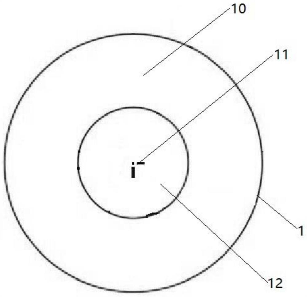
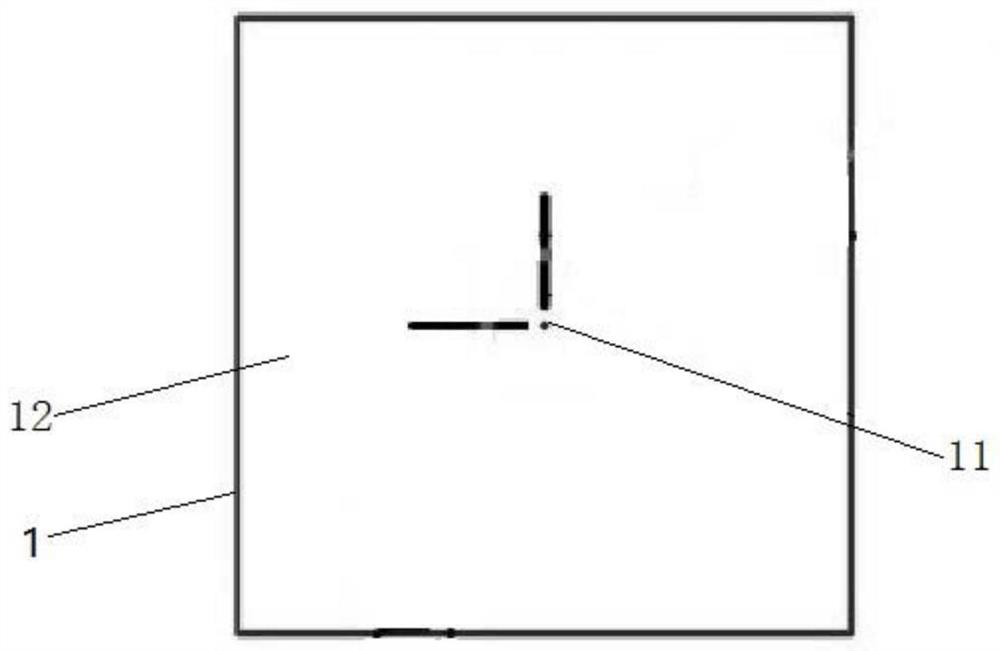
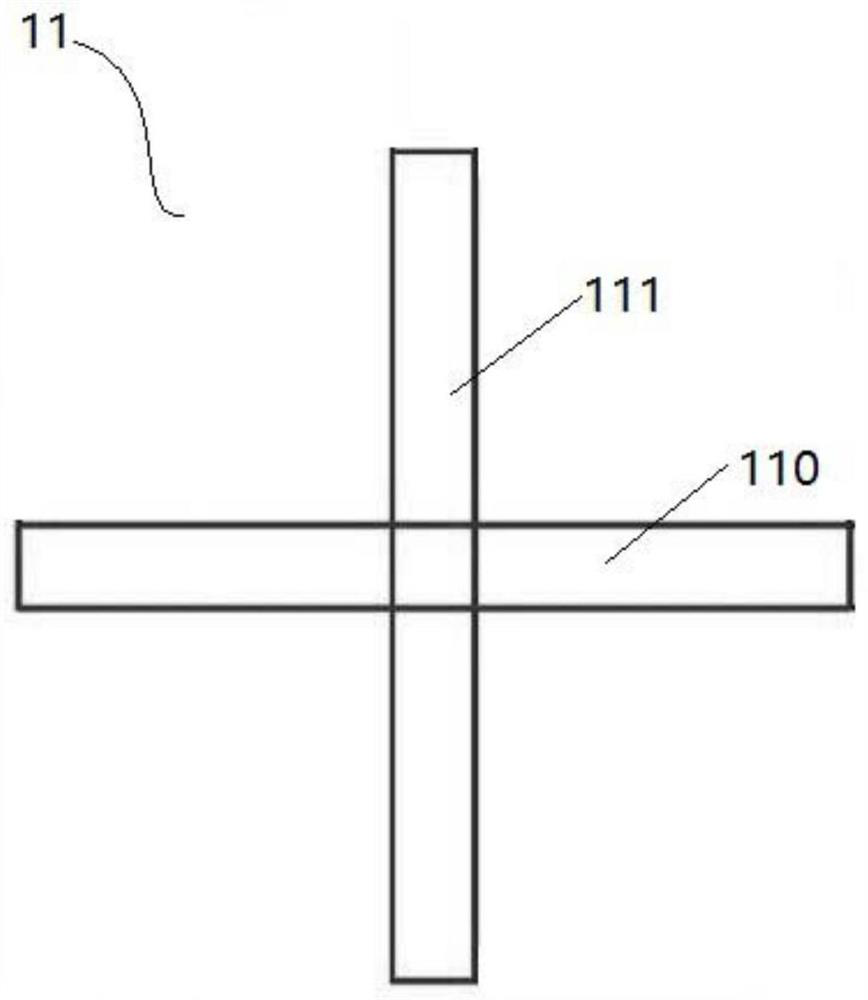
[0059] see Figure 1 to Figure 6 , a kind of object-loading glassware provided by the present embodiment, comprising: a body 1 and at least one fluorescent marker 11, the body 1 has a relative object-loading surface 10 and a positioning surface (not marked), and the object-loading surface 10 is suitable for placing the object to be Observing the sample (not shown) and setting the fluorescent marker 11, the positioning surface is suitable for fixing and positioning the object-carrying glassware on the electronically controlled stage of the fluorescence microscopy imaging device. The body 1 of the object-carrying glassware of this embodiment is an existing conventional confocal dish (such as figure 1 and Figure 4 shown) or slides (such as figure 2 and Figure 5 shown). The excitation wavelength and emission wavelength of the fluorescent marker 11 are different from the excitation wavelength and emission wavelength of the fluorescent substance of the sample to be observed, ...
Embodiment 2
[0066] For the fluorescent microscopic imaging device provided in this embodiment, see Figure 1 to Figure 8 , including an excitation light module (not shown), an electronically controlled stage, the object-carrying glassware of Example 1, an image acquisition module and a computer. Wherein the excitation light module is used to generate the laser beam as the excitation light; the electronically controlled stage includes an operating table 5, an object stage 2 that can be controlled by the operation table 5 to move in a horizontal plane, and an operable stage installed on the object stage 2. Table 5 controls the rotating module 3 that rotates relative to the object stage 2, and the operating table 5 can display the plane displacement of the object stage 2 and the rotation angle of the rotating module 3; The module 3 moves, and is used to place the sample to be observed, and the laser beam is focused on the fluorescent marker 11 on the object-carrying glassware and the sample ...
Embodiment 3
[0071] A method for using a fluorescence microscope imaging device provided in this embodiment includes the following steps:
[0072] S1. Fix the sample to be observed on the rotating module 3 of the electronically controlled stage;
[0073] S2. Find the fluorescent marker 11 on the object-carrying glassware in the field of view of the corresponding magnification, and judge whether the fluorescent marker 11 in the field of view matches the standard cross on the display screen or the imaging software interface. Control the horizontal displacement and rotation angle of the stage so that the fluorescent marker coincides with the standard cross, and then zero-adjust the displacement and rotation angle of the electronically controlled stage displayed at this moment to calibrate the origin position;
[0074] S3. Adjust the electronically controlled stage and find the target observation area of the sample to be observed in the field of view, and record the displacement and rotation...
PUM
| Property | Measurement | Unit |
|---|---|---|
| diameter | aaaaa | aaaaa |
Abstract
Description
Claims
Application Information
 - R&D
- Intellectual Property
- Life Sciences
- Materials
- Tech Scout
- Unparalleled Data Quality
- Higher Quality Content
- 60% Fewer Hallucinations
Browse by: Latest US Patents, China's latest patents, Technical Efficacy Thesaurus, Application Domain, Technology Topic, Popular Technical Reports.
© 2025 PatSnap. All rights reserved.Legal|Privacy policy|Modern Slavery Act Transparency Statement|Sitemap|About US| Contact US: help@patsnap.com